The task this week was to create the schematic, board layout and then mill the simple LED circuit board.
Autodesk Eagle is the circuit-board software that we used > Installing it was relatively easy as it was just a simple installation but to get the correct components for the FAB LAB, downloading the library of parts was done. This is to ensure that all of the pads are the correct size and can therefore be soldered easily.
This is the guide that I used > https://fablabbrighton.github.io/digital-fabrication-module/guides/guide-draw-circuit-in-eagle
Once you know where the library of parts is, it is relatively simple to use, but keeping it tidy is important to have an easy to read schematic and peace of mind that you have connected everything correctly.
Method for creating a new document
File > New Project > Right Click on the project > New > Schematic — Open in new window
Add Part > Search using *part* > All components that have 1206FAB as an option should be chosen

List of parts required is
- Red LED
- 1KOhm Resistor
- 10 KOhm Resistor
- Un-polarised Capacitor
- Omron Switch
- Resonator
- FTDI Header
- ISP header
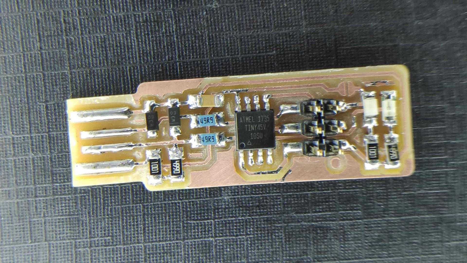
- ATtiny44
Add all of the components to the schematic then change the values of the resistors and capacitor.
Right click on the component and click value > Type in the correct value so that you can use you schematic for soldering late on and correctly refer to it.
Moving on to Board

Generate Board > click OK on message box


Move components and rotate them to the orientation that is going to best suit the board layout

Change width of the trace in the top bar when drawing the traces
Change the tolerance : Tools > DRC > Clearance
Check errors : Tools > Errors
If any errors are due to the schematic, then that will need to be altered. However if the errors are due to clearance errors and traces slightly crossing, these will show up and can be fixed relatively easily. Most of the time they can be fixed in EAGLE, by either drawing the trace again and choosing a slightly different path, however if the stepping in the movement of the trace is annoying, Adobe Illustrator can be used to alter the traces.
The next step is to move it to Adobe Illustrator: File > Export > DXF > ensure scale isnt change and you save it in a suitable location.


In Adobe illustrator the main aim is to remove all line and text, leaving only the traces, pads and the outline of the board > The traces may need altering slightly from the EAGLE file so this is when you would do that.
This is when you would add a logo if you wanted to.
The outline width should be set to 3-5mm as this the components and the edge of the board enough clearance
The artboard now needs to be set the artwork size > this can be done in a simple step > Objects > Artboards > Fit to Artwork Bounds
This is a critical step to ensure the two tool paths generated have the same origin point and therefore match.
Print this as PDF to ensure the components fit. I chose to increase the width of the pads for the FTDI header to 5mm as they didn’t fit with the printout.

Save as a PNG > tick the box saying use artboard > 1000dpi > save somewhere you can find it easily

Go to > fabmodules.org > upload you PNG by selecting PNG from the drop down menu

> Select Roland Mill > PCB Traces for the traces and outline for the outline > invert the image
> set the x0 y0 and z0 to 0
> Set the yhome, xhome to 0 and the zhome to 10

> Set the tool Diameter to 0.4mm for traces ; 1mm for outline > no. of offsets to 0 for a test toolpath
The tool path should be generated when you click calculate

This is a critical check to ensure that you board will work > Make sure none of the toolpaths merge together. They can overlap but not merge.

Roland Mill
The mill is very easy to set up and has an automatic tool change which speed up the work.
Setting the x and y origin is simply selecting which axis and using the hand wheel to control how far across the cutter is.
Setting the z origin requires more skill > Turn on the spindle to full speed > select z axis > get it close using the hand wheel > change the step distance to reduce how fast the z-axis moves with the hand wheel > get the spindle to just touching the copper ; you should see a small amount of white power appear when you get close enough
Change the tool bit to the correct one for the operation > menu > click over to the one which says tools > select tool 5 for doing the traces > tool 1 for the outline
Load up the file using the blue square in the bottom corner > add your file to the menu and delete any others >
Send to the cnc and ensure that it doesn’t crash by watching it >
Once finished load the outline file and change the tool bit as above > Start the outline and wait for it to finish
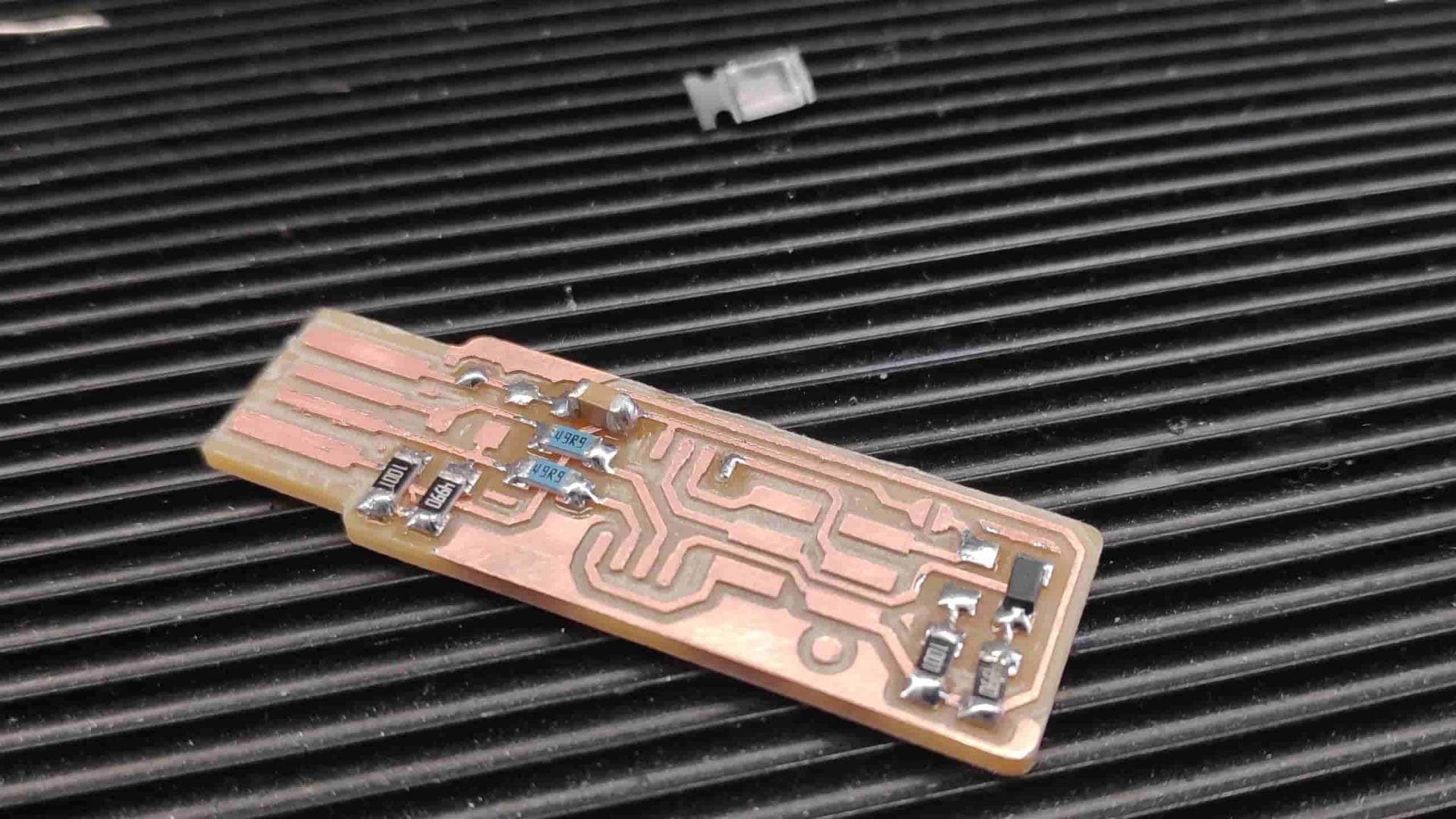
Remove the finished PCB using a scraper and clean up any rough edges

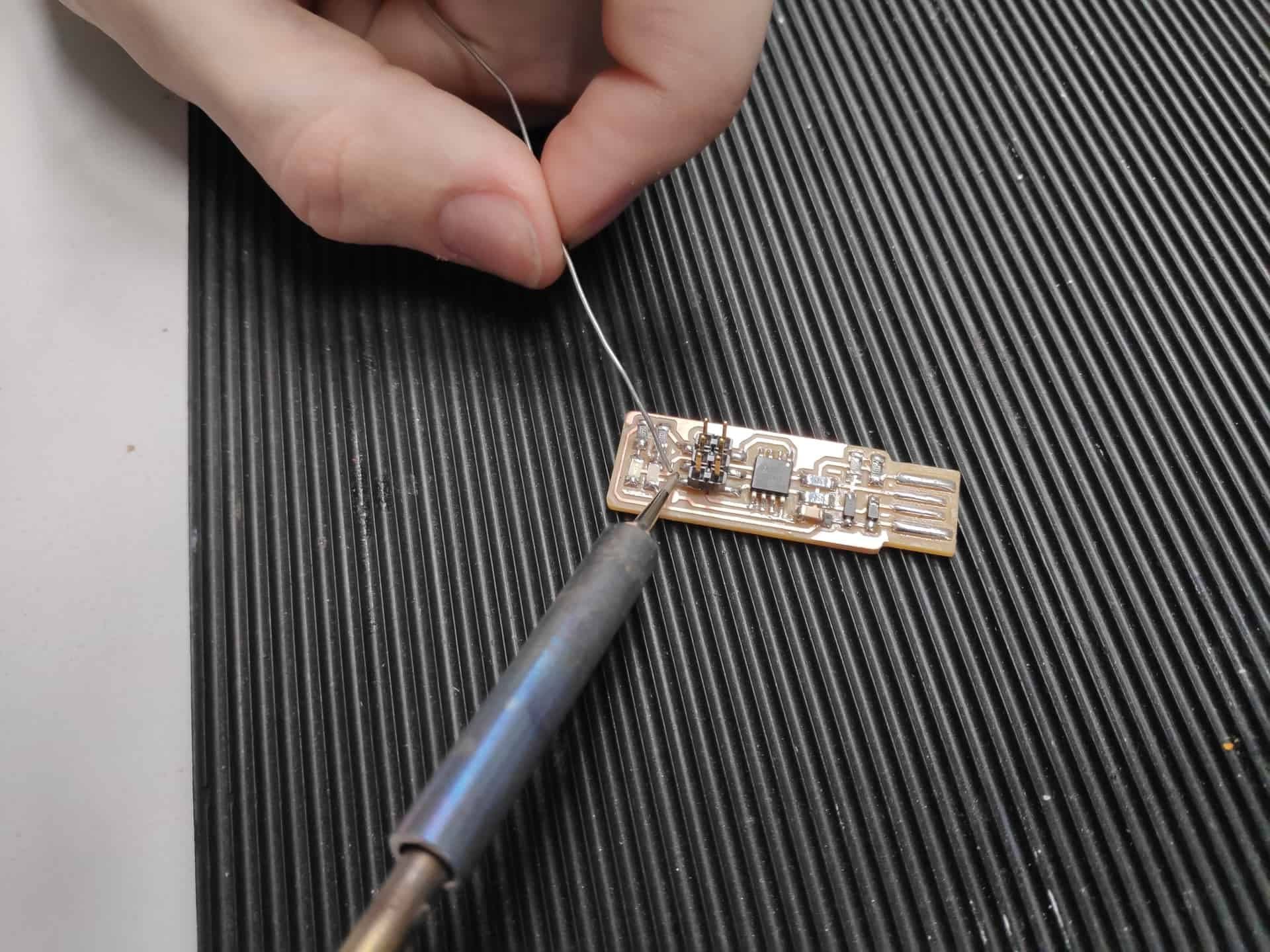
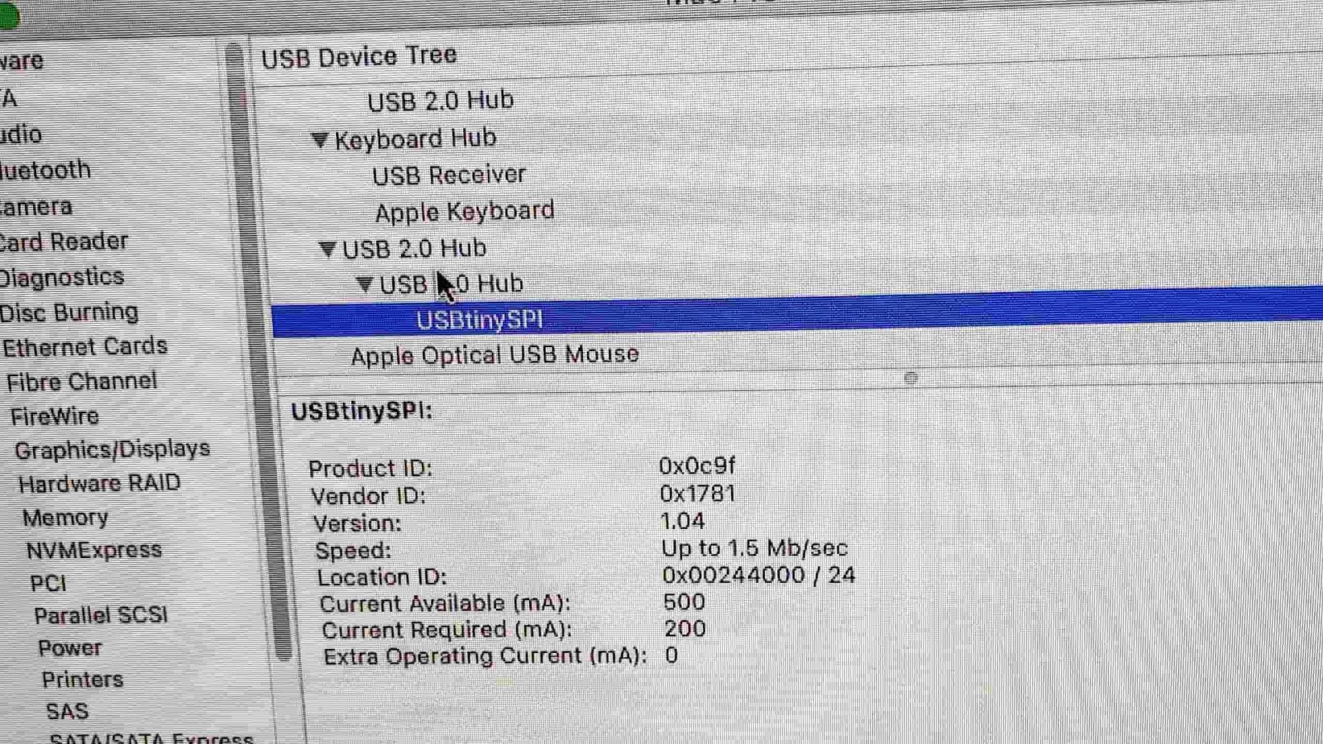
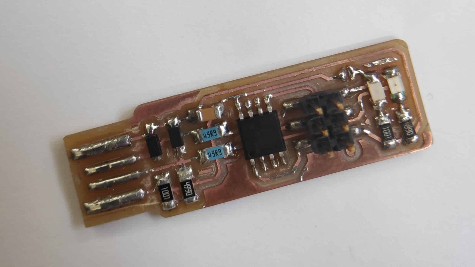
Solder the components on as in last weeks blog.