Increasing the accessibility of sustainable shaving to the majority of users by modifying an existing product; a Gillette or a Wilkinson Sword razor.
3 Week Project as part of the Other Today Studio at the University of Brighton 2nd year BSc
Identifying and Modifying an Existing Product
Starting with a photo brainstorm, 3 HMWs were set out which could be used to fulfill the brief. I decided to move forward with ‘How might we increase the sustainability of shaving’. After some initial research and my own existing knowledge, there are countless ways of making shaving sustainable, which have already been around for over a hundred years. It’s the larger companies saturating the market with disposable razors which has prevented wider audiences from using them. I decided to then make the change to ‘How might we make sustainable shaving more accessible’, which I felt was a more accurate view of the problem. This also met some of the insights which I was already looking at such as giving control back to the user, reducing built in obsolescence and increasing the lifespan of a product through reuse and repair
The tool caddy stores worksite hand tools using waste Tyvek sheets commonly found on construction sites.
3 Week Project as part of the Other Today Studio at University of Brighton 2nd Product Design
What have I done?
My project began with an interest in using a textile as the sheet material. Early on I focused on fabrics such as canvas for use in a wallet or similar application. While exploring materials, I came across ‘Mighty Wallet’; a wallet made from a Tyvek envelope. I often see Tyvek in skips so decided to research Tyvek further. Several people online have used the material for tote bags, drawstring bags and the like, however this is from virgin rolls of tyvek not offcuts. Tyvek do offer a recycling system for its products but it is highly inaccessible and offers no benefits to the construction companies.
This is my supply chain intercept point, providing an alternative to throwing away the material into skips. I could either remove the waste Tyvek from skips when they get sorted after collection, or work with the construction companies to set aside the Tyvek scraps to be sent via post as a bundle would be quite light. Alternatively a local rep could collect offcuts from several worksites and send it to the manufacturer in a larger bundle. This would save them money from skips costs and prevent this useful material from entering the landfill.
I wanted the product to stick to the materials origins as much as possible, ensuring that the product didn’t have far to be sold, so I focused on something for the worksite, such as tool storage. Storing tools on a worksite in a well organised manner is essential to an efficient building process so I saw producing a strong bag to hold the essentials from an inexpensive material as an opportunity.
Research into origami and different folding methods for paper worked well for finding the strongest and most space efficient storage method. The traditional method of producing pockets uses oddly shaped material and leaves the material proud which can catch and tear on worksite obstructions when not being used. The origami folds I used keeps the pockets flat when not being used.
Leaving it with a clean aesthetic was important such as hiding the stitches, but the strength of the joints was paramount, where these folds came into play. I also has very little waste and fold into itself to ship as its own envelope.
Research
Material Research Ended in Tyvek being chosen as the material to be used, and further research such as stitch length and thread tension was done to ensure the best project was made.
Tyvek Supply Chain
Iteration
Several iterations were made in terms of folds and interactions between the materials. Origami techniques were changed and altered from standard variations.
As I was originally going to do a wallet, some of the folds I used there could have been used in my final object.
The coin wallet was a good test, in terms of strength and the types of folds that can be used.
Both tyvek and paper were used for the testing of these folds.
Instructions for Manufacture
Below is the cut and fold list for the entire tool caddy. Depending the whether the end user or the manufacturer is making the caddy. It can be either hand sewn or machine sewn, which ever is avaliable.
30 x 150
Knife pleat fold at 50mm and 25mm
Repeat once
400 x 130
Knife pleat fold at 50mm and 25mm
Repeat 4 times
Vertical fold at 100mm
160 x 230
Knife pleat fold at 65mm and 30mm
Knife pleat fold at 125mm and 15mm
Vertical fold at 130mm
100 x 240
Knife pleat fold at 40mm and 20mm
Repeat three times
740 x 80
Fold in half lengthways
600 x 420
Fold in half lengthways to make 600 x 210
Crease every 73mm
Fold vertically 10mm at the open end of long edge
Cut 10mm at 73mm creases where vertical fold has been made
Final Product
Final Product as posted on the left and as assembled on the right
Potential in the project
I found the material quite nice to sew and cut as it is very much like paper. It’s easy to cut square and fold in the right places. I see a lot of potential in other products that could be made with the material, from smaller items such as a safety glasses case, or stuff sacks for waterproof clothing to an entire storage rack for a van or digger. Very specific tool kits for jobs could be made in the material as tool rolls, such as a daily maintenance kit for an excavator.
The main benefits of using this material are of course the interception of a waste stream, with very standard sizes of offcuts. They are almost always full width offcuts, and therefore designs can easily be made parametrically according the the length of offcuts.
Since the material can be laser cut means these parametric designs can be simply cut out without any complications, depending on the material available.
Changes to the current design would include making it entirely machine sewable and placing a solid bottom into the caddy to make it more stable (although this isn’t within the brief).
Started making wallets from one tyvek envelope as a DIY project without having to sew anything together and was easily customisable as users can just draw on their wallet.
A polyester based material used for wrapping houses to keep the moisture out
Could be an offcut based product, using scraps from construction sites to produce wallets as and when they have enough material.
Main outcomes of this were sewing details which are covered on the hand written A3 sheet
Origami book
Folding Techniques for Designers: From Sheet to Form – Book by Paul Jackson
Research regarding types of fold to create the tool pockets was essential and this book helped me focus in on certain types of folds. The final fold concept was the knife pleat which I adapted to be a pocket.
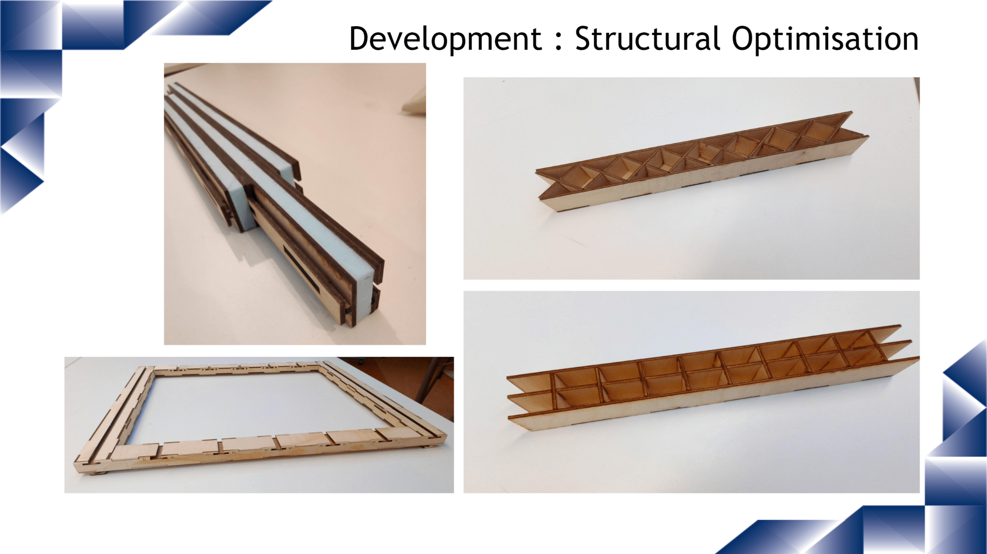
This project was based around moving homes constantly. Our aim was to produce collapsible furniture that could be easily adapted to everyday life and small spaces that students and the like would normally have to live in.
Various modifications and improvements made to my Land Rover either in progress or completed.
Summer 2018
Swapping Springs for the front of the Land Rover.
The previous owner put the wrong springs on each side when he restored the vehicle, causing the vehicle to lean to one side as the springs are sided. The springs were taken on and swapped, with a small repair done and a de-rust and oil to improve the ride of the car.
Christmas 2018
The Project over Christmas was to restore the dashboard of the car. Since this is where the driver sits 95% of the time it is nice to have a well covered and good looking area to drive from. In the process of the physical restoration of the dashboard, I restored the gauges, trim and heater matrix of the vehicle. The main dash pieces were fairly rusty and required lots of welding, which was quite difficult due to how thin the steel was!The first section was about renewing the metal by welding sheet steel after bending into the space which was left after cutting out the rusted metal.
As part of the dashboard remake, the wiring needed a lot of attention. This stage I got the lights working properly and added a relay to them, which made them brighter and reduced the chance of a fire in the cab, and the high voltage didn’t travel through the dashboard.
Here are the recondition gauges which were rather difficult to get the bezels and glass back into.
This is some of the wiring in the engine bay which the previous owner did. Rather shoddy and was replaced by adding new connectors and cleaning it up.
Below is the trailer hitch which was causing a lot of problems as it wasn’t wired properly. This was ignored until all the wiring was working and then was simply spliced into the new wiring.
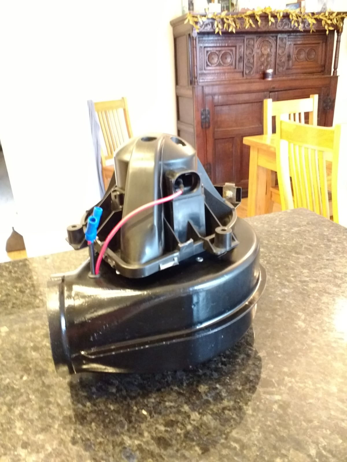
Heater Matrix and Fan
The existing fan was shot – Spending £100 for a new motor was a no go at that point, especially since fans from Mini Coopers were £12 and blow better and faster. All the original mountings were used and so an original motor could be used in the future if required.
Using kitchen extractor pipe also saved some money which could be better spent on other parts of the project (£80 for a short section was again ridiculous). The heater core was reused after a good flush and clean up and paint of the box.
Learning about the resistor and switch mechanism was interesting and that something that simple could be used the control the speed of the fan.
I did of course take apart the motor to see how it worked and if it could have been saved.
Rims
No fancy alloys for me thank goodness. Good old steel rims. A lot of angle grinding and old paint and rust and they were ready to paint. Red oxide and then some hand painted 2k limestone and they were ready to go. Just a day to mount the tyres before the Claygate Flower Show classic car event.
Classic Car Show
It was very nice to set up next to some amazing classic cars and have so many people come and talk to me about their experiences with Land Rover and the good memories that they still remember from their childhoods.
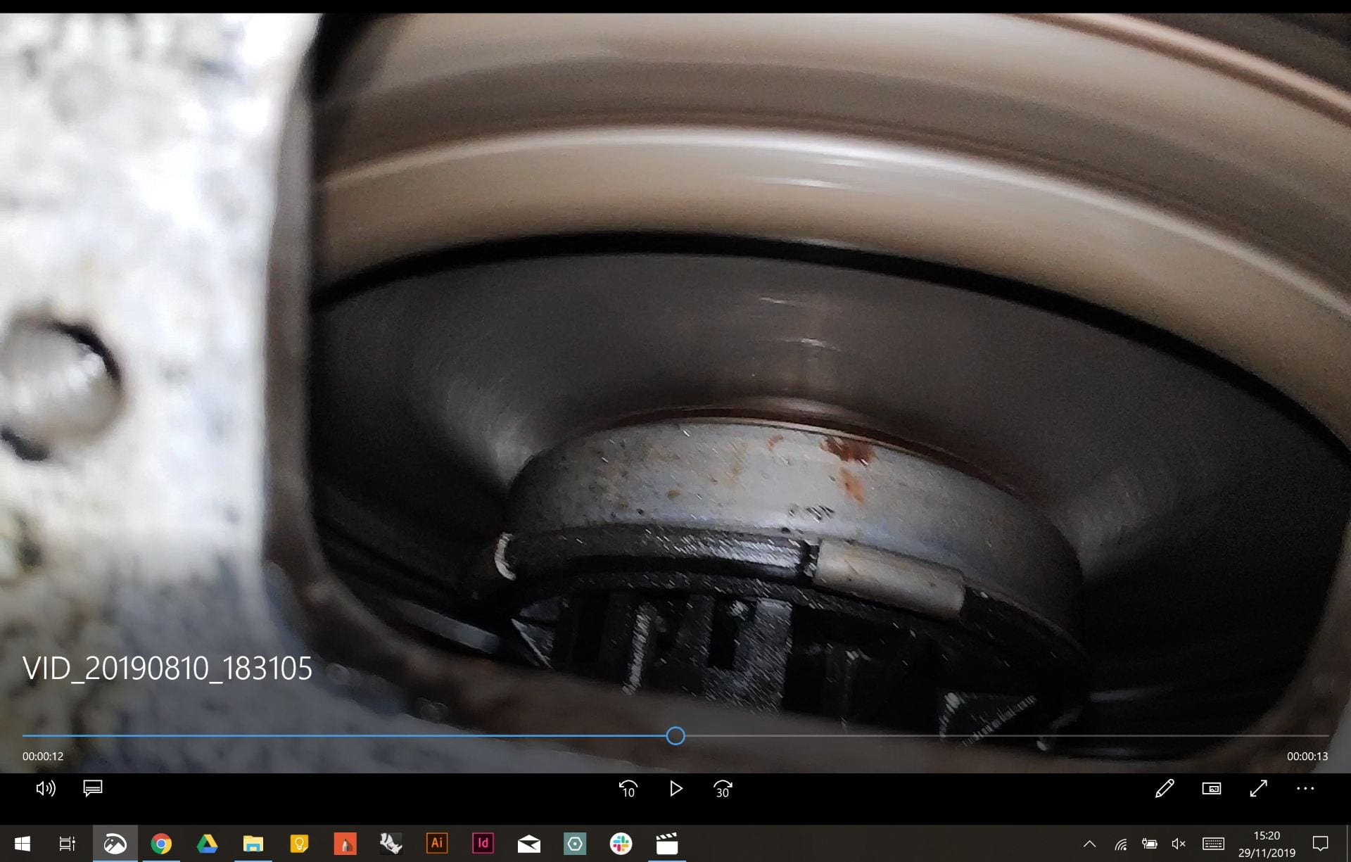
Clutch Bearing…….or mainshaft bearing……or both?
The noise was more of an irritant that a problem, according to the haynes manual.
Using an endoscope I tried to diagnose the clutch bearing but it seemed all good. The mainshaft of the transmission was the next culprit and therefore it was decided to take of the hub at the back. Again everything was fine and was left after replacing the spring clip and lock nut at the end of the mainshaft.
Seating for the rear
It is rather uncomfortable in the back especially without seats. Rather than buying them I decided I could make a higher quality seat for less money and it would also fit much better.
It it to be mounted to the rails n the side and would be a single cushion on the back two benches.
Still a work in progress but they will be covered in the same material as the dashboard, with a stockinette underneath.
The final week task was to program a robot which would move by itself and avoid objects
Unfortunately this wasn’t completed due to time constraints, although most of the code for the movements was completed and fully working
The board was attached to the chassis with metal standoff – which did short the board out – however it was sorted out by replacing them with plastic ones
Two stepper motors were used to control the robot, one on each side.
There is a breakout board on top of the arduino, which allows for easy plugging in and out of the stepper motors
Coding
Below is the coding used for the control
Where the breaks are for the left, right, forward, and reverse, the position of the output pins have been changed, so that the stepper motor activated the different magnets in a different order, which changes the direciton.
The left and right have one wheel going forward and one going backwards, therefore turning on the spot, similar to how tanks rotate using their tracks
Here the robot is programmed to run the command for about 16 seconds, after which it will stop moving
Wire up the arduino using these following instructions
VCC (Red) to 5V
Ground/GND (Black) to GND
SDA (Blue) to A4
SCL (Yellow) to A5
The code used was downloaded adn the library installed in the specific location. Ensure that the LCD drivers are included in the same folder
#include <Wire.h>  // Comes with Arduino IDE
// Get the LCD I2C Library here:
// https://bitbucket.org/fmalpartida/new-liquidcrystal/downloads

#include <LiquidCrystal_I2C.h>

// set the LCD address to 0x27 for a 20 chars 4 line display
// Set the pins on the I2C chip used for LCD connections:
//                    addr, en,rw,rs,d4,d5,d6,d7,bl,blpol
LiquidCrystal_I2C lcd(0x27, 2, 1, 0, 4, 5, 6, 7, 3, POSITIVE);  // Set the LCD I2C address

void setup()   /*----( SETUP: RUNS ONCE )----*/
{
  Serial.begin(9600);  // Used to type in characters
  lcd.begin(20,4);         // initialize the lcd for 20 chars 4 lines, turn on backlight

  //-------- Write characters on the display ------------------
  // NOTE: Cursor Position: Lines and Characters start at 0
  // lcd.setCursor(Horizontal position,Line)

  lcd.setCursor(4,0); //Start at character 4 on line 0
  lcd.print("GO BACK");
  lcd.setCursor(4,1);  //Next start at character 6 on line 1
  lcd.print("TO");
  delay(1000);
  lcd.setCursor(4,2);
  lcd.print("THE");
  delay(1000);
  lcd.setCursor(4,3);
  lcd.print("SHADOWS");

  delay(4000);
  // Wait and then tell user they can start the Serial Monitor and type in characters to
  // Display. (Set Serial Monitor option to "No Line Ending")
  lcd.setCursor(0,0); //Start at character 0 on line 0

  lcd.clear(); //Clears the screen.
  lcd.print("Start Serial Monitor");
  lcd.setCursor(0,1);
  lcd.print("Type characters");
  lcd.setCursor(0,2);
  lcd.print("to display");


}/*--(end setup )---*/


void loop()   /*----( LOOP: RUNS CONSTANTLY )----*/
{
  {
    // when characters arrive over the serial port...
    if (Serial.available()) {
      // wait a bit for the entire message to arrive
      delay(100);
      // clear the screen
      lcd.clear();
      // read all the available characters
      while (Serial.available() > 0) {
        // display each character to the LCD
        lcd.write(Serial.read());
      }
    }
  }

}/* --(end main loop )-- */
Displaying ultrasonic measurements on LCD screen
This is the code for running the screen and the ultrasound sensor all as the same time, displaying the range in cm to the LCD screen attached to the the arduino
It is a combination of both the ultrasonic sketch downloaded from student central and the above LCD sketch. The basics behind it is setting up the ultrasonic sensor as an input and keeping the LCD as an output
After some playing around to change the refresh rate (delay) of the LCD and where the stationary text was it looked good and could accurately read the distance if it was within its range
#include <Wire.h> // Comes with Arduino IDE
// Get the LCD I2C Library here:
// https://bitbucket.org/fmalpartida/new-liquidcrystal/downloads

#include <LiquidCrystal_I2C.h>

// set the LCD address to 0x27 for a 20 chars 4 line display
// Set the pins on the I2C chip used for LCD connections:
// addr, en,rw,rs,d4,d5,d6,d7,bl,blpol
LiquidCrystal_I2C lcd(0x27, 2, 1, 0, 4, 5, 6, 7, 3, POSITIVE); // Set the LCD I2C address

#define echoPin 7 // Echo Pin
#define trigPin 8 // Trigger Pin
#define LEDPin 13 // Onboard LED

int maximumRange = 200; // Maximum range needed
int minimumRange = 0; // Minimum range needed
long duration;
long distance; // Duration used to calculate distance

void setup() {
Serial.begin(9600);
lcd.begin(20,4);
pinMode(trigPin, OUTPUT);
pinMode(echoPin, INPUT);
pinMode(LEDPin, OUTPUT);

lcd.setCursor(0,0);
lcd.print("Range Finder");
lcd.setCursor(0,1);
lcd.print("Current Distance : ");
lcd.setCursor(7,2);
lcd.print("cm");

}

void loop() {
/* The following trigPin/echoPin cycle is used to determine the
distance of the nearest object by bouncing soundwaves off of it. */
digitalWrite(trigPin, LOW);
delayMicroseconds(2);

digitalWrite(trigPin, HIGH);
delayMicroseconds(10);

digitalWrite(trigPin, LOW);
duration = pulseIn(echoPin, HIGH); // Measures the length of a pulse on echoPin in microseconds
//waits for the pin to go HIGH, starts timing, then waits for the pin to go LOW and stops timing.
//Returns the length of the pulse in microseconds.

//Calculate the distance (in cm) based on the speed of sound.
distance = duration/58.2;

if (distance >= maximumRange || distance <= minimumRange){

lcd.clear();
lcd.setCursor(0,0);
lcd.print("Range Finder");
lcd.setCursor(0,1);
lcd.print("Current Distance : ");
lcd.setCursor(4,2);
lcd.print(distance);
lcd.setCursor(7,2);
lcd.print("cm");
delay(300);
digitalWrite(LEDPin, HIGH);

}
else {
lcd.clear();
lcd.setCursor(0,0);
lcd.print("Range Finder");
lcd.setCursor(0,1);
lcd.print("Current Distance : ");
lcd.setCursor(4,2);
lcd.print(distance);
lcd.setCursor(7,2);
lcd.print("cm");
delay(300);
digitalWrite(LEDPin, LOW);
}
delay(500);
}
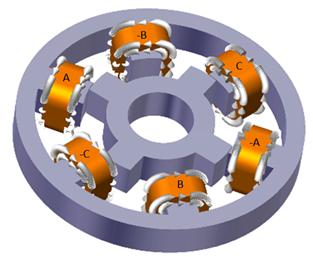
A stepper motor uses opposing electromagnets to create rotation. The different number of steps are determined by the number of poles on each the stator and the rotor.
There are several different types of stepper motor, depending on the use case and the size that is required. The main types are :
Permanent magnet stepper > These use permanent magnets in the rotor and electromagnets in the rotor, using attraction and repulsion to create rotation
Uses
Stepper motors can be used for all sorts of CNC controlled devices such as 3D printer or CNC routers.
Mechanical arms such as those used for assembly of cars etc will use stepper motors to obtain exact position repeatably
Any automated machinery that requires exact positions to be returned to, will use stepper motor as they are very precise int he increments of rotation that they can do.
How to drive a stepper motor
Wave forms that drive a stepper motor
Turning coils on and off > Transistors are electric dimmer switches which can be used as on off switches for stepper motors
The loop will run through all of the bracketed coded indefinitely
delay(2) is the amount of ms left between that line of code and the next, which determines how fast or slow the motor will turn. The smaller the number, the faster it spins.
> ‘unsigned char’ allows you to control all of the same variables in a sketch by only changing one value
unsigned char DelayTime = 255;
unsigned char LEDoutput = 2;

// the setup function runs once when you press reset or power the board
void setup() {
 // initialize digital pin LED_BUILTIN as an output.
 pinMode(LED_BUILTIN, OUTPUT);
 pinMode(LEDoutput, OUTPUT);
}

// the loop function runs over and over again forever
void loop() {
 digitalWrite(LEDoutput, HIGH);
 digitalWrite(LED_BUILTIN, HIGH);
 delay(DelayTime);
 digitalWrite(LEDoutput, LOW);
 digitalWrite(LED_BUILTIN, LOW);
 delay(DelayTime);
 DelayTime = DelayTime - 10;
 }
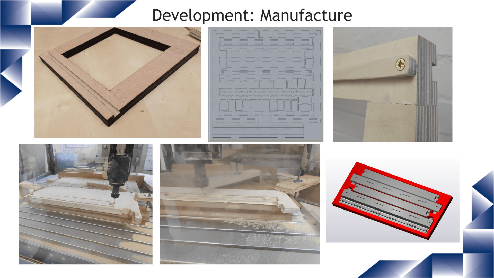
Most important is to know your cutter shape and size. Any features have to be designed in accordance to the diameter of the cutter as this will restrict how far and deep the slots between features can be.
Try and keep the cutter as big as possible as it will reduce cutting time as well as the chance of the cutter breaking or chipping.
If you are making a mould;just like the vacuum former; you will need to use draft angles even on small/short features.
Absolutely no undercuts as the CNC milling machine is unable to rotate the bed or spindle
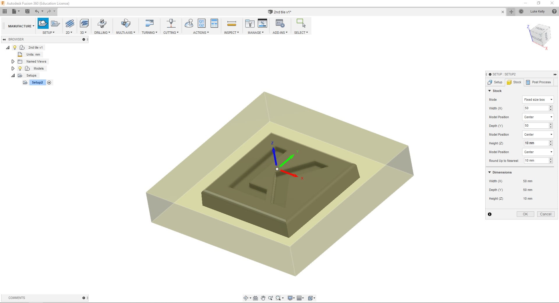
Using the design rules above create your tile using Fusion 360 – with the front place in CAD actually the top of your model – CNC’s use a different coordinate system
Move to the ‘MANUFACTURE’ tab
CAM Setup
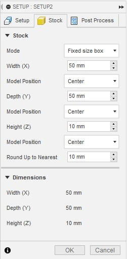
Click on ‘Setup’ > Ensure ‘Stock box point’ is selected in the origin box
Under the ‘Stock’ tab > Selected ‘Fixed box size’ Set to 50x50x10mm with ‘Centre’ selected for the other boxes ; I always select ‘Fixed size box’ as then I always know that the scale isn’t messed up and can work with the size of the raw stock much more easily
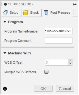
Under the Post-Process tab choose a suitable ‘Program Name/Number’ which includes enough details to not get confused with other versions of the file, in case you need to come back and change tool paths etc later
Milling Operations
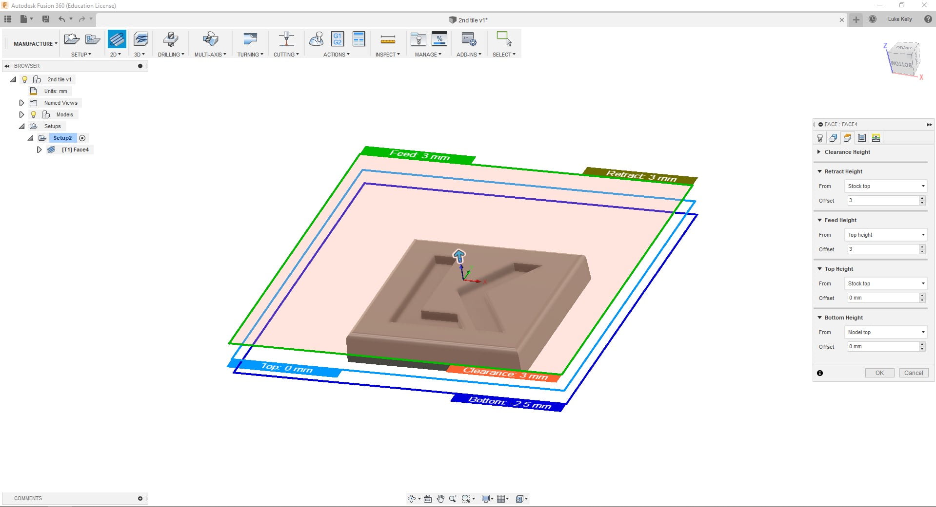
Right click on Setup > New Operation > ‘2D Milling’ > ‘Face’ ; For the first operation to get down to the correct level
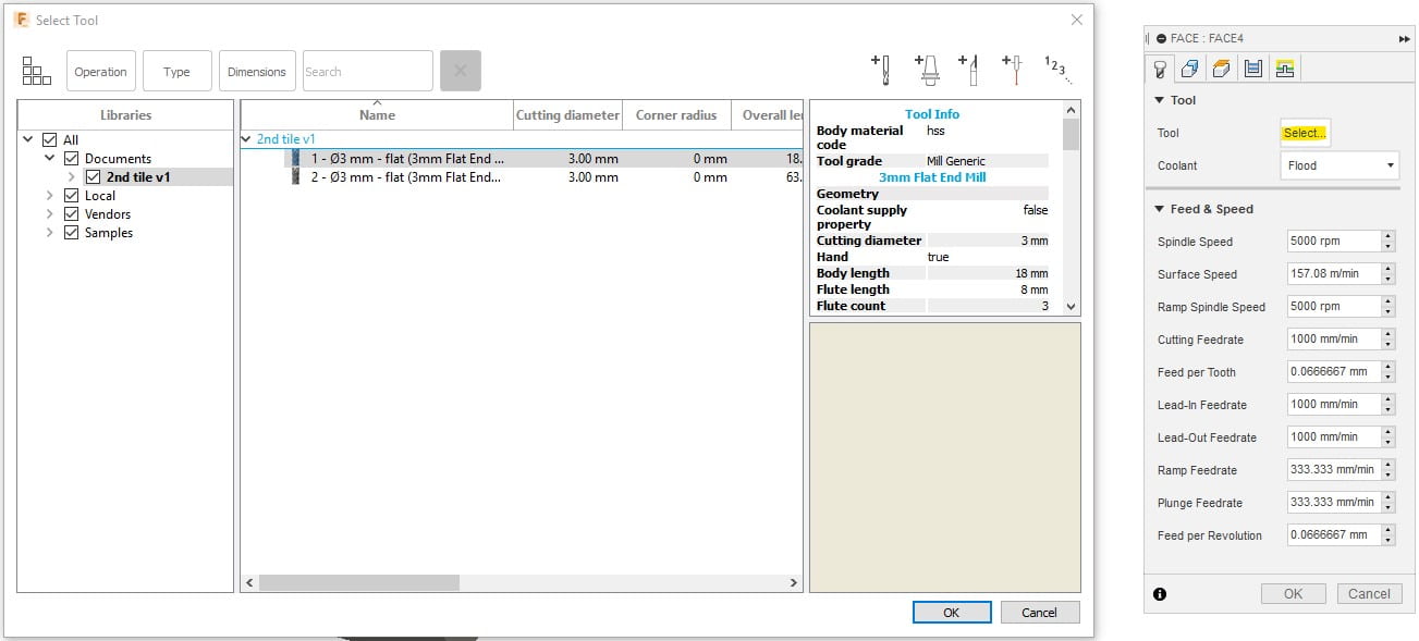
Select ‘Tool’ to create the new tool > Edit the highlighted settings which are the important ones for making this tile > click ‘OK’ and turn off coolant – OR choose from the existing tool selection > Samples > Metric – High Carbon Steel > φ3mm – flat (3mm Flat Endmill)
Go to the stock selections tab > ‘Select’ box next to ‘Stock Selections’ > Click on the top surface > this picks the level you want to mill down to
Heights tab > Set them all to from ‘Stock Top’ apart from depth which you can set to ‘Model Top’ > These are the levels your tool will retract to after each operation and shouldn’t be too close to the stock top nor too far to waste time
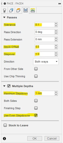
Passes tab > This sets how much material the tool can remove with one pass > General rule is half the width of the tool for step over and 1/3 of tool diameter for ‘stepdown’
Linking tab can be left as is. This controls the lead in and lead out
Complete these steps again for the next tool operations – the only difference should be the levels and the geometry > all of the tool data and offsets remain the same as above
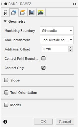
I use the ‘Ramp’ tool to cut the contour and pocket in the same operation > this just cuts out time in Fusion 360 by remove the need to go through the set up process for the operations separately
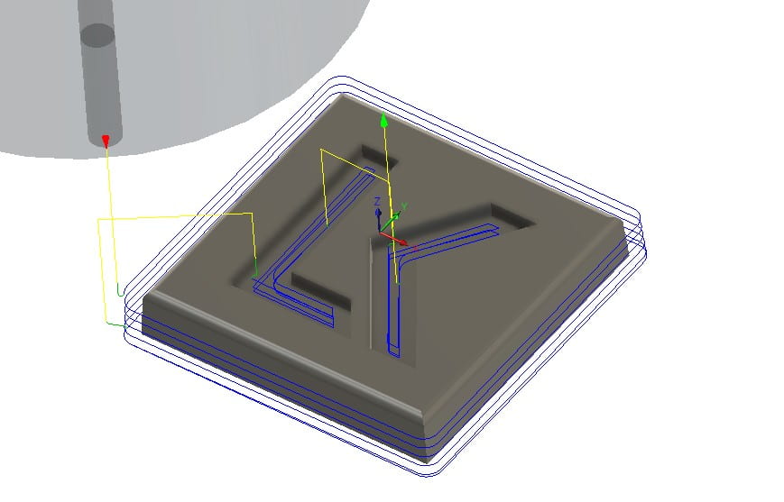
Check the tool path with the simulate function > Set the tool to be Shaft to remove the large tool holder blocking your view > Show stock > click play button at the base and ensure that all the material is removed > make sure that the mould left is exactly what you want to be left behind
Post Processor
Relatively simple > Click Generate and choose Grbl as the post processor > check you save it in a place that you can find it and check the file name is correct and identifiable
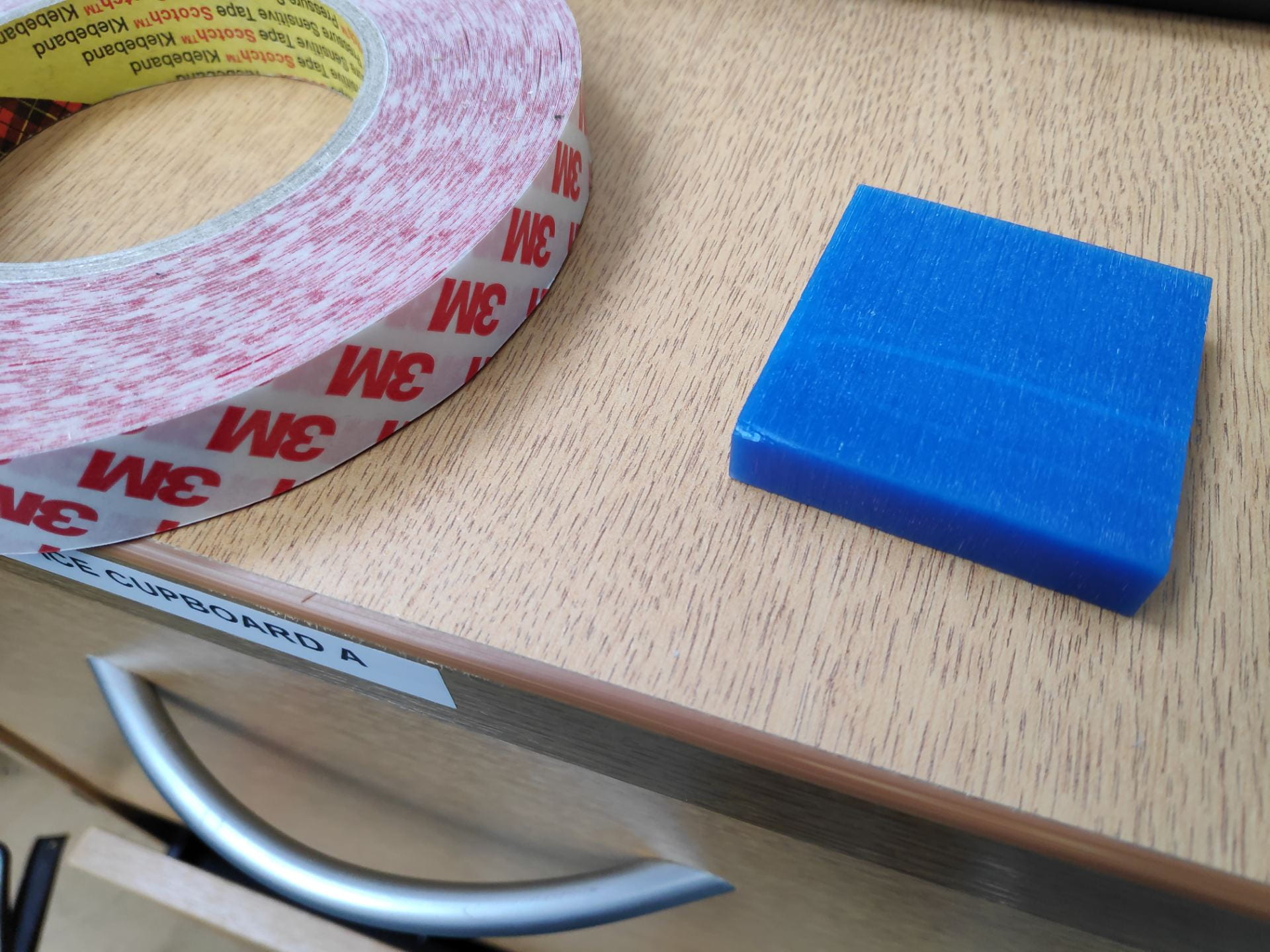
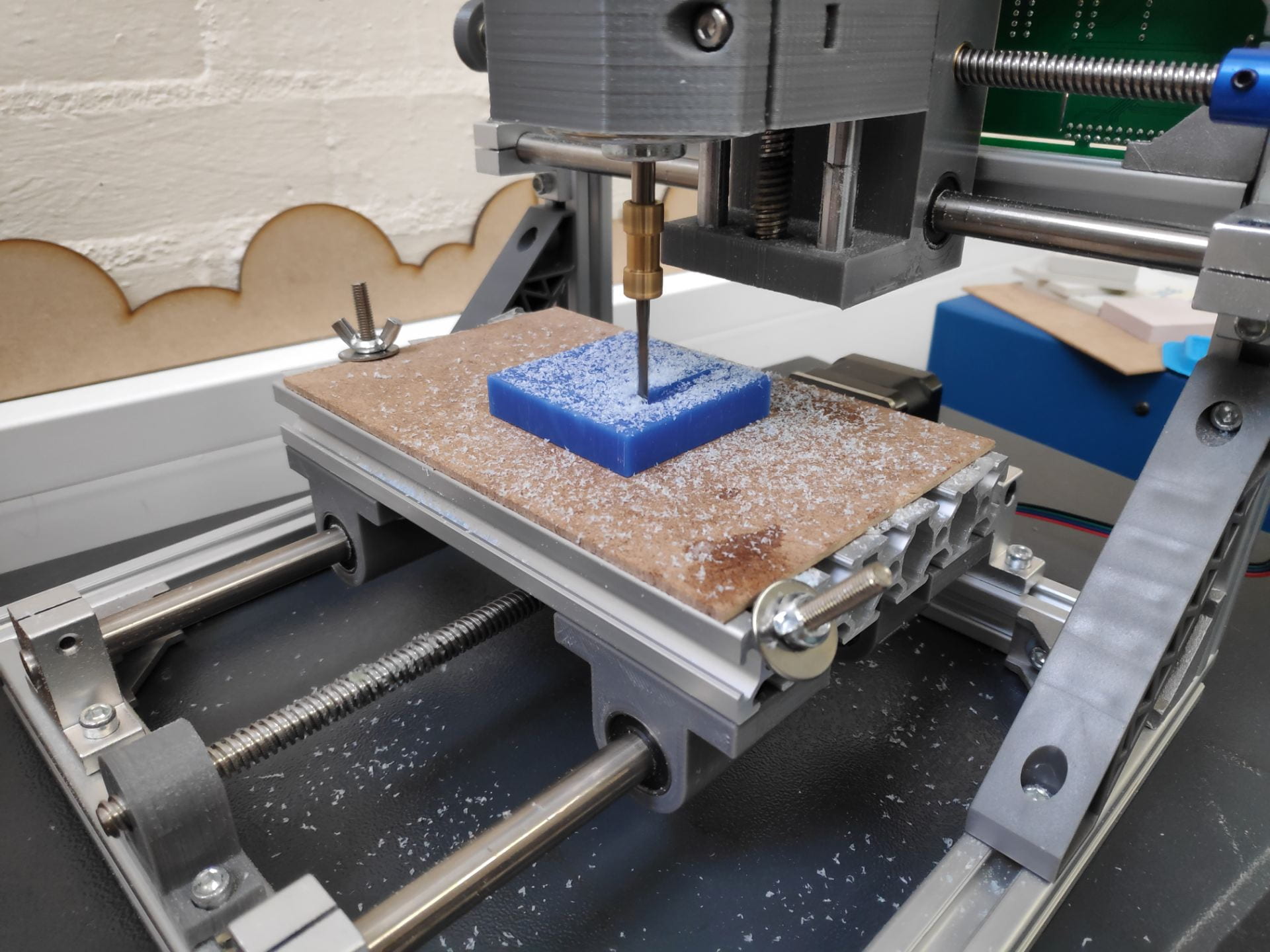
Prepare the mill, by removing any waste from previous milling operations and apply double sided tape to the block of wax that you will cut your tile on – attach the tile to the centre of the bed
Choose the cutter – use the one which you programmed in Fusion 360 – and install it on the machine. Two grub screws need to be tightened (one either side of the bit, as well as two for attaching it to the spindle)
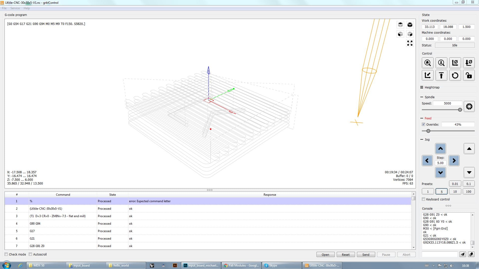
Load the GRBLcontrol program and use this to set the X and Y coordinates in the centre of the block of wax – click set home before moving on
Do a test cut by raising the z home position and cut the air above the wax for about a minute just to check speeds, feeds and if anything looks amiss.
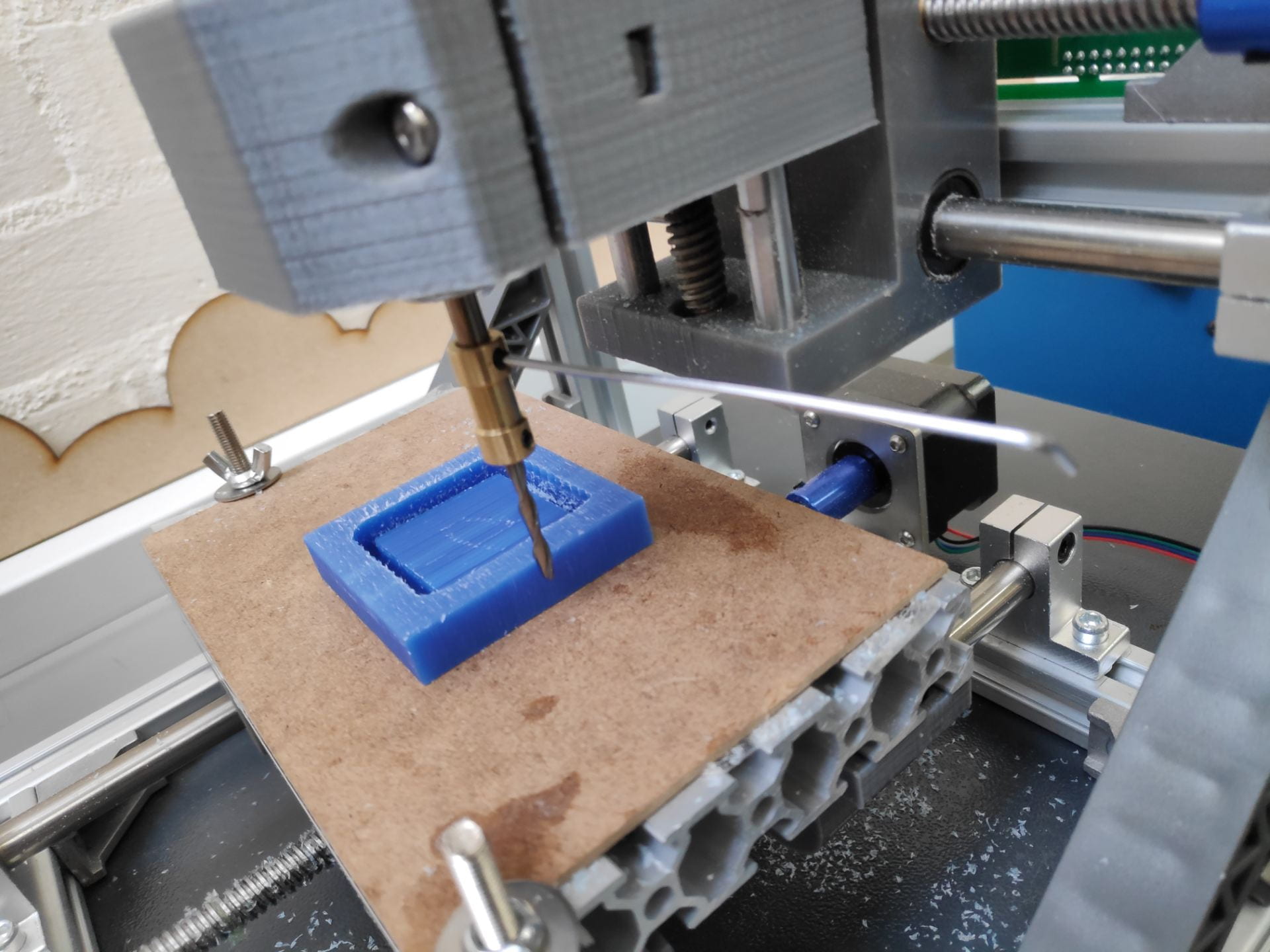
Setting the z height – Very similar to that of the PCB milling machine – turn on the spindle and slowly move the z height down until it just kisses the wax, then set the home and lift it up slightly so it doesn’t crash when you start your operation
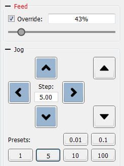
Depending on the material override the feed to ~75% for pink foam or ~30% for wax
Click send
I stopped the milling machine at the end of the occasional operation to give it a vacuum and remove the waste material – This will improve the finish especially of harder materials as well as reduce the chance of the tool breaking.
Keep watching it until the operation has finished then remove from the machine bed using a pry tool
Vacuum the bed, ways, screw threads etc as well as the surrounding area, ensuring any tape is also remove from your part as well – leave it as you want to find it
Deburr you wax part using a fingernail or the end of a ruler – but don’t press too hard
Problems
Ensure that the milling cutter is tightened down before each use – it wasn’t checked in my case and it just popped off when it had nearly finished (no harm done!)
This meant that the operation had to be started again and therefore took much longer than it should have
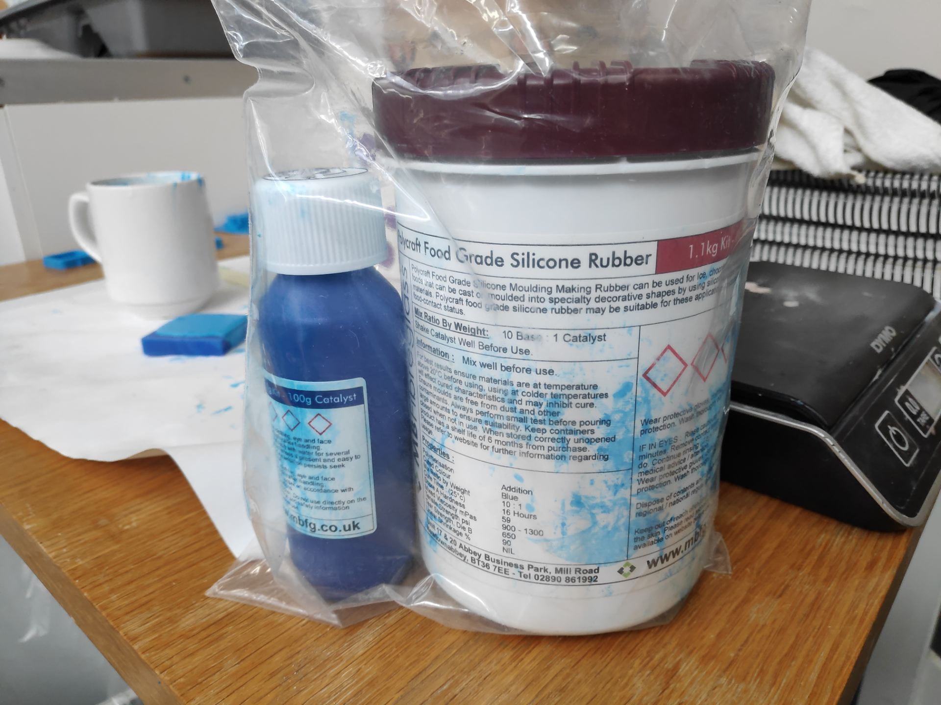
Casting with food grade condensation cure silicone
Prepare a work area with some covering on the work surface as it can be quite messy
Wear disposable gloves as well as a lab coat to protect clothing
Use scale to measure out the silicone and curing agent in a coffee mug 1 to 10 ratio much easier to mix in than a disposable cup (excess can be peeled out after it has set)
Mix well using a plastic stirring rod and leave for 10 minutes to let the bubbles rise to the surface
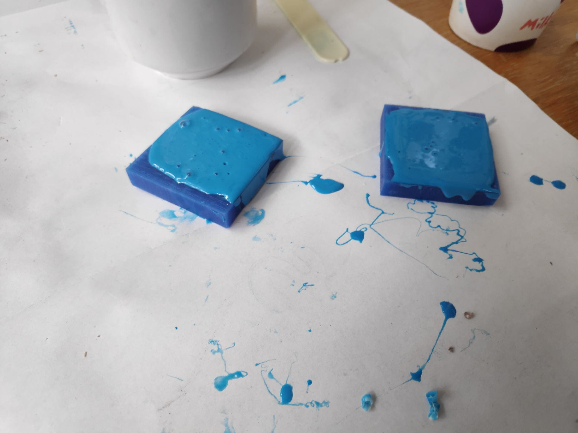
Push into your wax mould using the stirring rod and fill up any others it you have any silicone left – try and remove any pockets of air
It is quite good at self levelling so leave the silicone proud of the top of the mould so there is material left to fill any voids as it settles.
Leave to set for at least 24hrs
Peel it out of the wax mould and you should have a mould to cast into
Chocolate Moulding
Moulding with chocolate is relatively easy, just take your time and don’t burn it by putting too much heat into it too quickly. I tried to use the microwave to melt it but in suck small amounts found that difficult.
The best way is to melt the chocolate in a glass bowl over boiling water. Seeing as its a small amount I only needed to boil the kettle and transfer the water to the jug and place the bowl over this (with the water level just below the level of the bowl).
The chocolate came out of the mould relatively easily, and the details were quite prominent. One issue however is the flashing on the outside of the chocolate indicating that I overfilled the mould. It is also down to the ball nose end mill not leaving a square edge at the base of the chocolate, instead leaving a flange.
3d Scanning can be done in multiple ways and at multiple price points, either with handheld scanner for an iPad all the way up to full systems, e.g for car manufactures to scan clay cars.
They also have different degrees of accuracy, with hand held scanners being less expensive they will also produce less detailed scans, but still very much usable.
Photos to wire frame to surfaces
This is the process of taking a few images and importing them into a CAD software such as Rhino and creating a line drawing from the outside of the image and then building up a CAD model from that. This will produce a very accurate CAD model with clean surfaces, however it might be harder to get in the fine details for the thing you were taking photos of. You may also struggle if the object is very complex or if it has lots of small details on one face, making it difficult to get side profiles of these features.
The main steps are:
Use a curve tool for draw the rough shape
Clean these up with either rebuild curve or by dragging points on the curve
Add in additional details such as the mouse wheel
Use this wire frame to create surfaces which can be then used to 3D print
Photogrammetry
This is the process of taking lots of photos and importing them into a CAD software creating a 3D image using relative distances between the photos. This can normally done with an app as well as a corresponding desktop application as it can be quite intensive to create the model from the photos depending on its complexity.
3D scanning
3D scanning was done using scanners which attached to an iPad, making them very convenient to use; https://structure.io/
The scanning process is relatively simple as the app tells you what to do at each stage
Launch the app and locate the box on the screen on the object that you wish to scan
Change the size of the box to suit that of the object
Click start and slowly move around the object ensuring that all angles are covered. It will tell you from time to time to stop and wait while it picks up all of the surface details.
Send this via email from the app to start the next process
At this stage you can either use this scan to create a wire frame in a program such as Rhino and create the surfaces as above, or import it into a mesh altering software such as Meshmixer.
Rebuilding
As in the photo to wire frame method, the aim of this is to create a wire frame from the 3D model and then create new surfaces, which will overall give you a much better surface finish, but will be impossible to do on something organic such as an arm.
The 3D scan is brought in and rectangular surfaces are put in to create the main wire frames. Project to surface command is then used to obtain the exact curves. These can then be cleaned up or redrawn as above and then surfaces created using on to the multiple surface tools. This is the the most time consuming method but produces the best results and the highest quality surfaces.
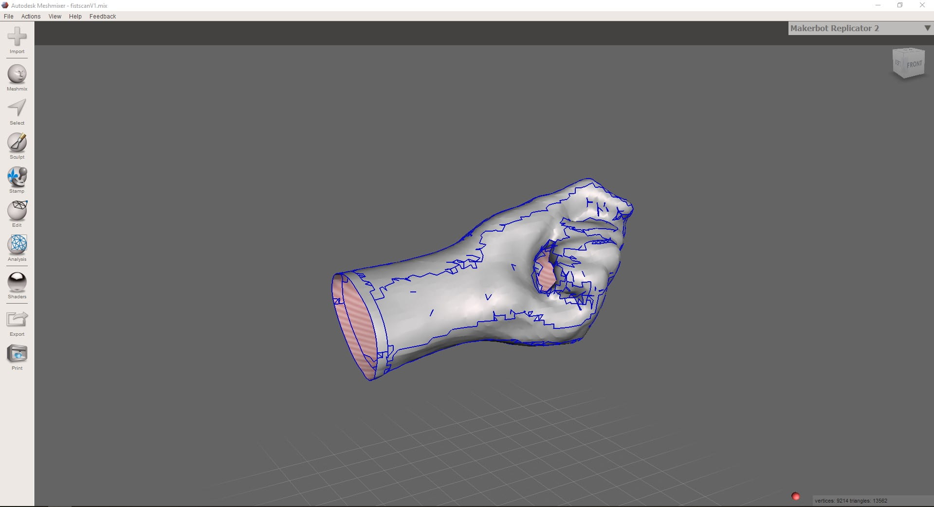
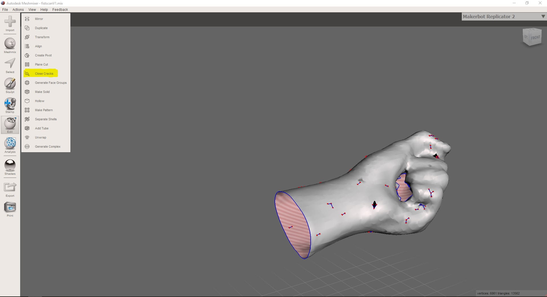
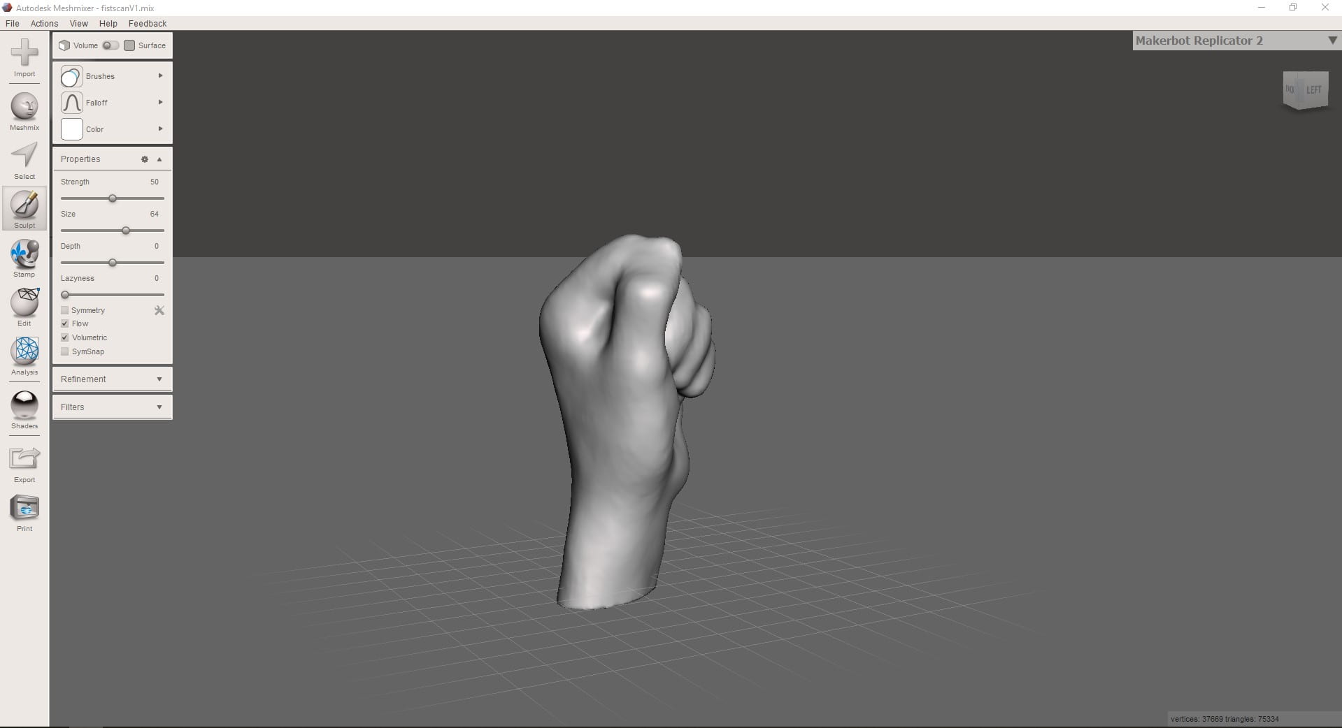
Meshmixer
Meshmixer is a free software which allows you to create and edit meshes and 3D objects, such as 3D scans.
Import you wire and use the simplest tools to reduce your work.
Use the simplest commands first such as ‘Close Gaps’ – this command will almost always turn a lot of work into very little.
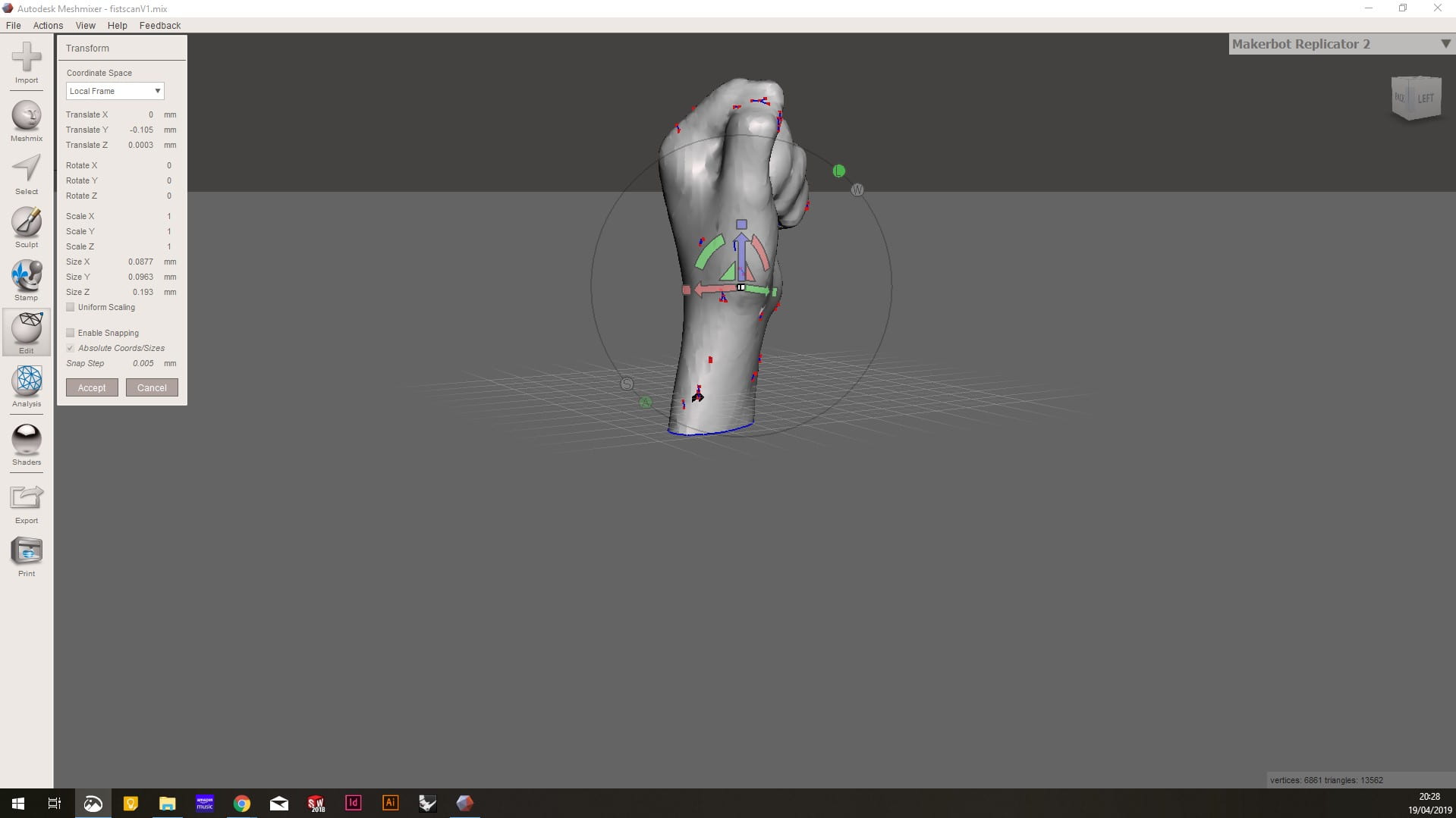
The next best thing is to try and make the object a solid. I found it best to cap the base of the hand and set it at the desired angle. Use the Translate tool for this.
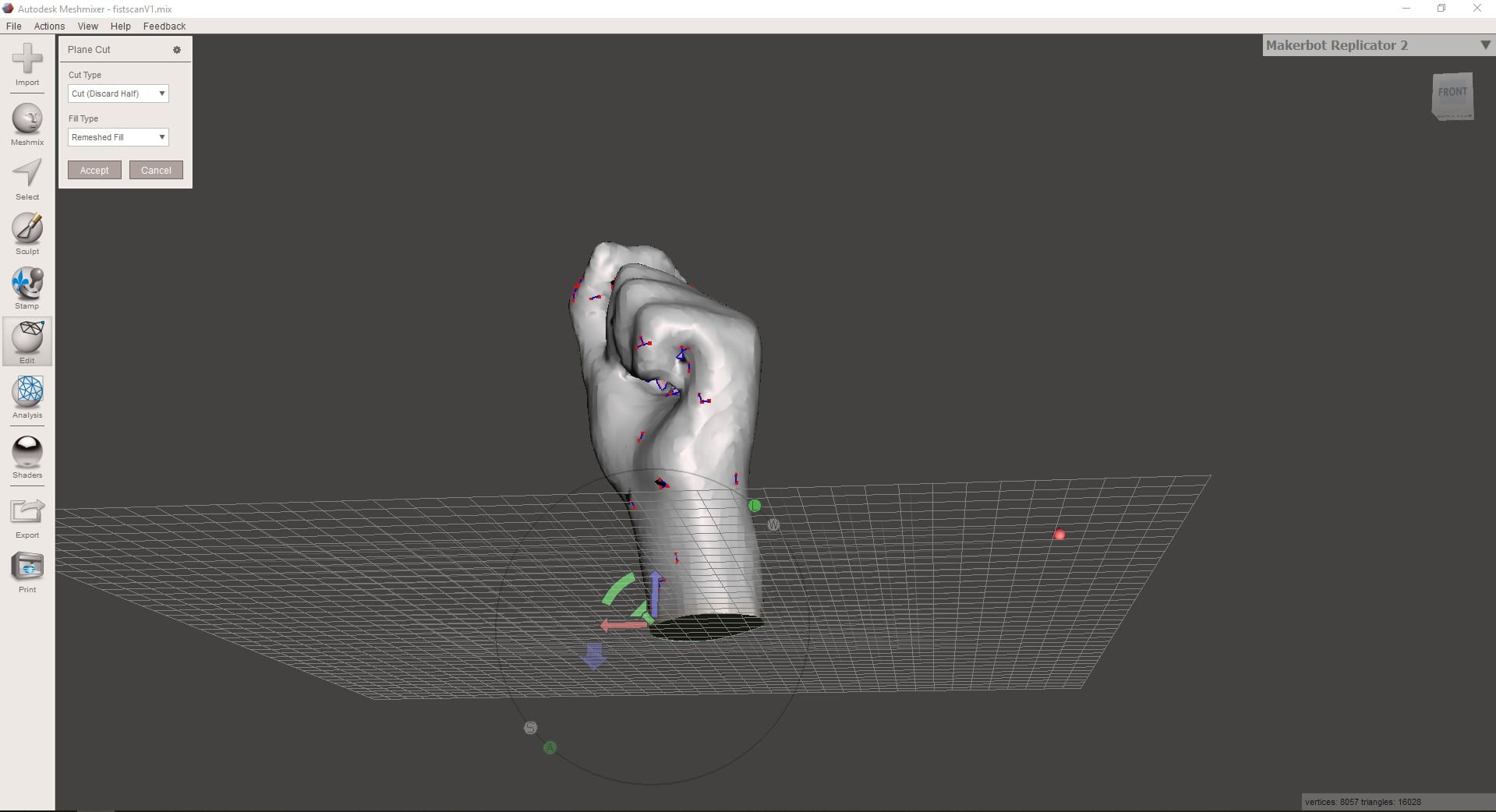
Capping the base of the hand is done using the ‘Plane Cut’ tool. This acts as a knife and cuts a flat surface through your object.
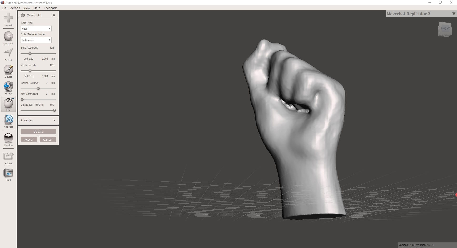
Use the tool ‘Make Solid’ to convert your shape into a solid. It isn’t perfect and left the space under my fingers a mess, mostly due to the lack of light when scanning and therefore details couldn’t be determined.
Using the Sculpting tools the errors made by the scanner such as mussing out under the fingers can be corrected.
This video shows the entire process of sculpting and editing the scan
Load the document into Ultimaker Cura which allows you to preview and edit the 3D printing details
Once loaded, orientate the model into the desired place and ensure that it has imported in at the correct size. It is important to think about the orientation due to the layers as any overhangs which may require supports. Reducing the number of supports will reduce the print time as well as decrease the need for cleaning up after printing.
Click Slice in the bottom right, then preview when this is completed.
Under print settings you can choose the layer height – main time saver along with infill % – This will require the slice command to be run again
Preview of the layers being built up; showing the support material
The task this week was to program the board that we made using the CNC router. There are several levels to this week, some being ‘simple’ and some being advanced.
The main goal was to upload some sort of program to our Echo Hello World Plus board and ensure that it completed the function that the program was supposed to do.
This gives you access to the aTtiny boards and programmer
Loading the correct Settings
> Tools > Board > ATtiny24/44/84
> Tools > Processor > ATtiny44
> Tools > Clock > External 20MHz
> Tools > Programmer > USBtinyISP
Plug into a power supply with 5V > GND 1st pin on ISP > +5v is the 3rd on the ISP
Burning the Bootloader
> Tools > Burn Bootloader
This originally didn’t work on Windows and therefore we switched to MAC
Programming
The first sketch tested was the Blink sketch from the > Examples > 01.Basics > Blink
The code required us to define which pin was the LED pin in order for it to work. This was worked out by using the pinout diagram. > Pin PB2 was connected to the LED and therefore the Arduino pin for this was no. 8.> Change all of the the LED_BUILTIN pins to 8
> Click Upload (Top menu)
Fade
The Fade sketch is very similar to the Blink > Again change all of the LED_BUILTIN to 8
Button Sketch
> Again it is an example sketch
> Change the ledPin on the constants to 8
> Change the buttonPin on the constants to 7 (as worked out from the Pinout Diagram
This is where we encountered problems due to the sketch being uploading but the LED would either flicker or not come on at all.
After some further reading on the following websites, it might be due to not having an internal pullup resistor enabled.
// constants won't change. They're used here to set pin numbers:
const intbuttonPin =8;// the number of the pushbutton pin
const intledPin =7;// the number of the LED pin// variables will change:int buttonState =0;// variable for reading the pushbutton statusvoidsetup(){// initialize the LED pin as an output:pinMode(ledPin,OUTPUT);// initialize the pushbutton pin as an input:pinMode(buttonPin,INPUT_PULLUP);}voidloop(){// read the state of the pushbutton value:
buttonState =digitalRead(buttonPin);// check if the pushbutton is pressed. If it is, the buttonState is HIGH:if(buttonState ==HIGH){// turn LED on:digitalWrite(ledPin,HIGH);}else{// turn LED off:digitalWrite(ledPin,LOW);}}
The only changes made to the existing button sketch was replacing INPUT with INPUT_PULLUP
Two sketches were recorded – one where the switch turned off the LED, and one which turned on the LED when it was pressed
The task this week was to create the schematic, board layout and then mill the simple LED circuit board.
Autodesk Eagle is the circuit-board software that we used > Installing it was relatively easy as it was just a simple installation but to get the correct components for the FAB LAB, downloading the library of parts was done. This is to ensure that all of the pads are the correct size and can therefore be soldered easily.
Once you know where the library of parts is, it is relatively simple to use, but keeping it tidy is important to have an easy to read schematic and peace of mind that you have connected everything correctly.
Method for creating a new document
File > New Project > Right Click on the project > New > Schematic — Open in new window
Add Part > Search using *part* > All components that have 1206FAB as an option should be chosen
List of parts required is
Red LED
1KOhm Resistor
10 KOhm Resistor
Un-polarised Capacitor
Omron Switch
Resonator
FTDI Header
ISP header
ATtiny44
Add all of the components to the schematic then change the values of the resistors and capacitor.
Right click on the component and click value > Type in the correct value so that you can use you schematic for soldering late on and correctly refer to it.
Moving on to Board
Generate Board > click OK on message box
Move components and rotate them to the orientation that is going to best suit the board layout
Change width of the trace in the top bar when drawing the traces
Change the tolerance : Tools > DRC > Clearance
Check errors : Tools > Errors
If any errors are due to the schematic, then that will need to be altered. However if the errors are due to clearance errors and traces slightly crossing, these will show up and can be fixed relatively easily. Most of the time they can be fixed in EAGLE, by either drawing the trace again and choosing a slightly different path, however if the stepping in the movement of the trace is annoying, Adobe Illustrator can be used to alter the traces.
The next step is to move it to Adobe Illustrator: File > Export > DXF > ensure scale isnt change and you save it in a suitable location.
In Adobe illustrator the main aim is to remove all line and text, leaving only the traces, pads and the outline of the board > The traces may need altering slightly from the EAGLE file so this is when you would do that.
This is when you would add a logo if you wanted to.
The outline width should be set to 3-5mm as this the components and the edge of the board enough clearance
The artboard now needs to be set the artwork size > this can be done in a simple step > Objects > Artboards > Fit to Artwork Bounds
This is a critical step to ensure the two tool paths generated have the same origin point and therefore match.
Print this as PDF to ensure the components fit. I chose to increase the width of the pads for the FTDI header to 5mm as they didn’t fit with the printout.
Save as a PNG > tick the box saying use artboard > 1000dpi > save somewhere you can find it easily
Go to > fabmodules.org > upload you PNG by selecting PNG from the drop down menu
> Select Roland Mill > PCB Traces for the traces and outline for the outline > invert the image
> set the x0 y0 and z0 to 0
> Set the yhome, xhome to 0 and the zhome to 10
> Set the tool Diameter to 0.4mm for traces ; 1mm for outline > no. of offsets to 0 for a test toolpath
The tool path should be generated when you click calculate
This is a critical check to ensure that you board will work > Make sure none of the toolpaths merge together. They can overlap but not merge.
Roland Mill
The mill is very easy to set up and has an automatic tool change which speed up the work.
Setting the x and y origin is simply selecting which axis and using the hand wheel to control how far across the cutter is.
Setting the z origin requires more skill > Turn on the spindle to full speed > select z axis > get it close using the hand wheel > change the step distance to reduce how fast the z-axis moves with the hand wheel > get the spindle to just touching the copper ; you should see a small amount of white power appear when you get close enough
Change the tool bit to the correct one for the operation > menu > click over to the one which says tools > select tool 5 for doing the traces > tool 1 for the outline
Load up the file using the blue square in the bottom corner > add your file to the menu and delete any others >
Send to the cnc and ensure that it doesn’t crash by watching it >
Once finished load the outline file and change the tool bit as above > Start the outline and wait for it to finish
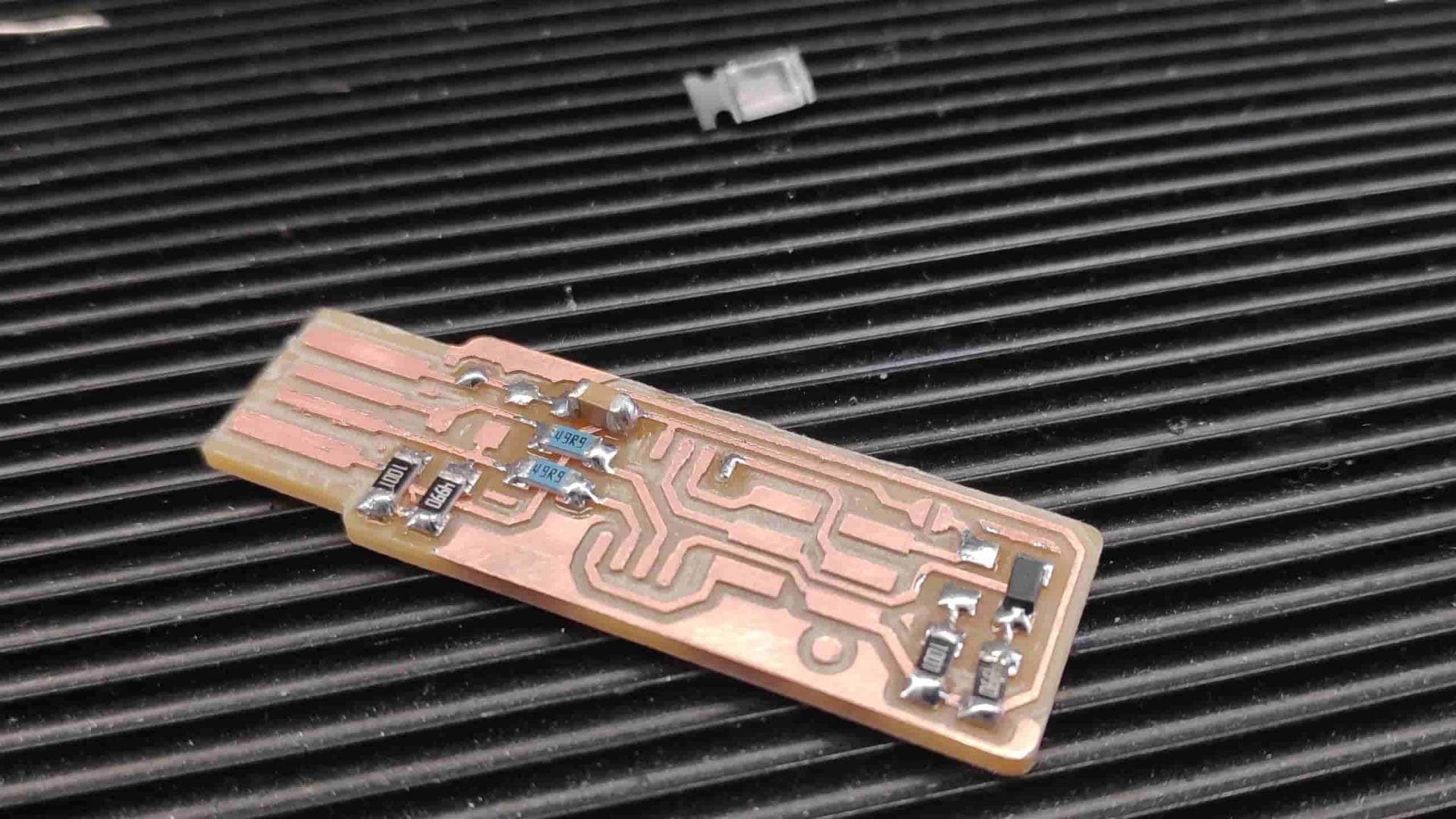
Remove the finished PCB using a scraper and clean up any rough edges
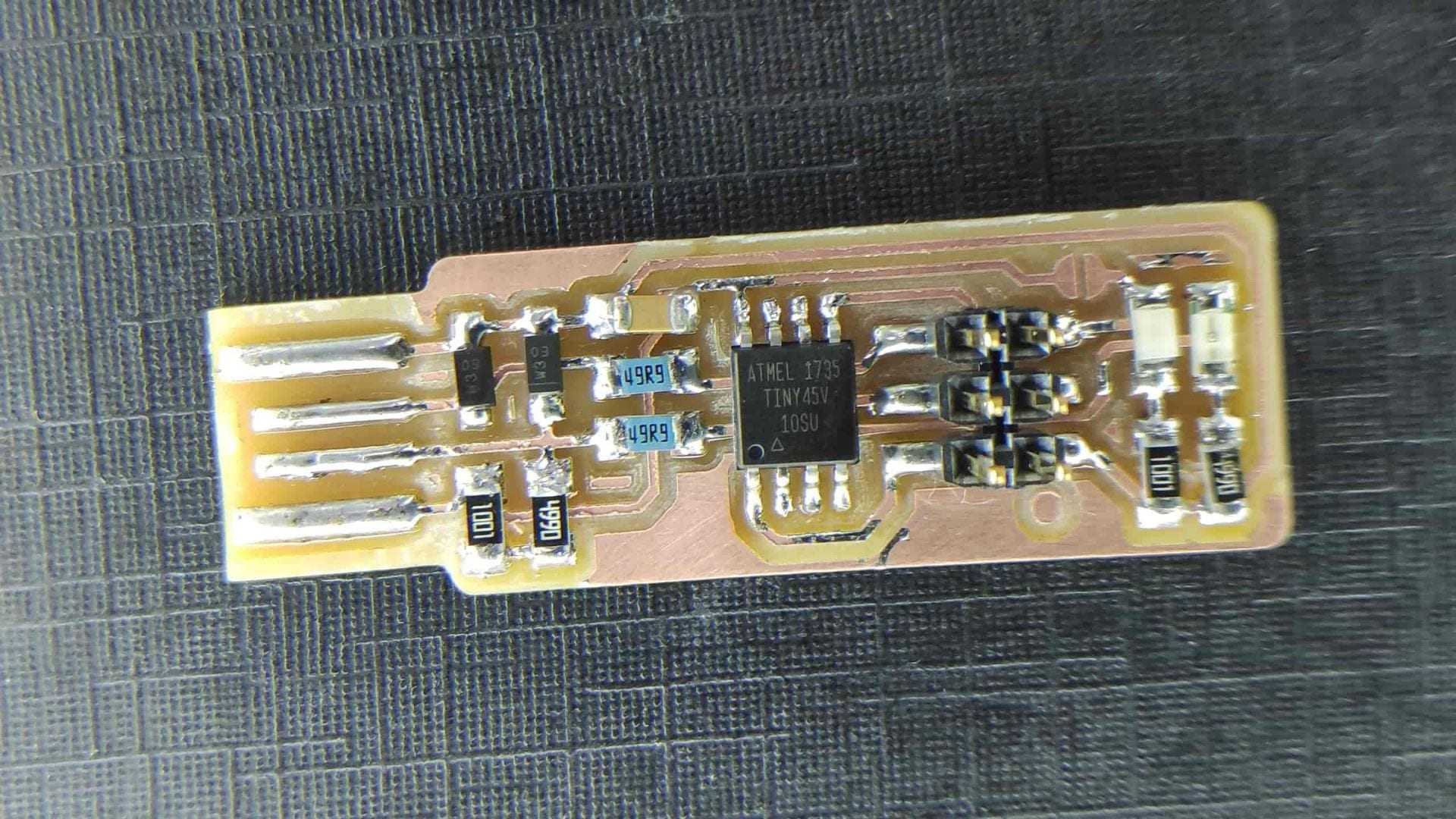
Surface mount components are very common and are what the majority of manufacturers will use due to the smaller size, compared to through components. It seems fairly easy to use them, although the mounting of these components, via soldering is vastly different to through hole components.
Through hole components have the obvious advantage of being self locating, so it is easy to manufacture. Surface mount components need to be held in place when soldering and so require skill to also locate them and make them straight.
Method
Prepare the board for soldering by washing it in soapy water to remove any oxidation that may have occurred since milling.
Gather all of the components and ensure you know what orientation they are supposed to be.
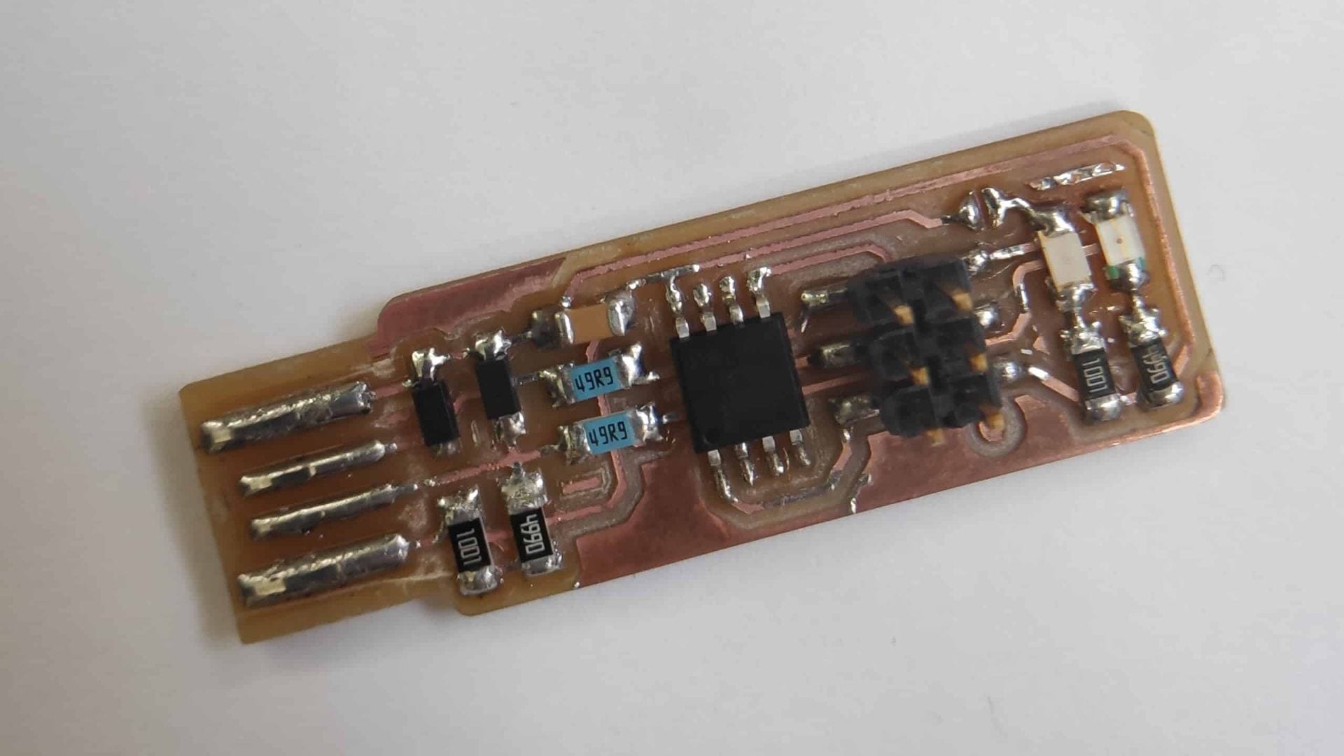
1x ATtiny45
2x 1kΩ resistors
2x 499Ω resistors
2x 49Ω resistors
2x 3.3v zener diodes
1x red LED
1x green LED
1x 100nF capacitor
1x 2×3 ISP header
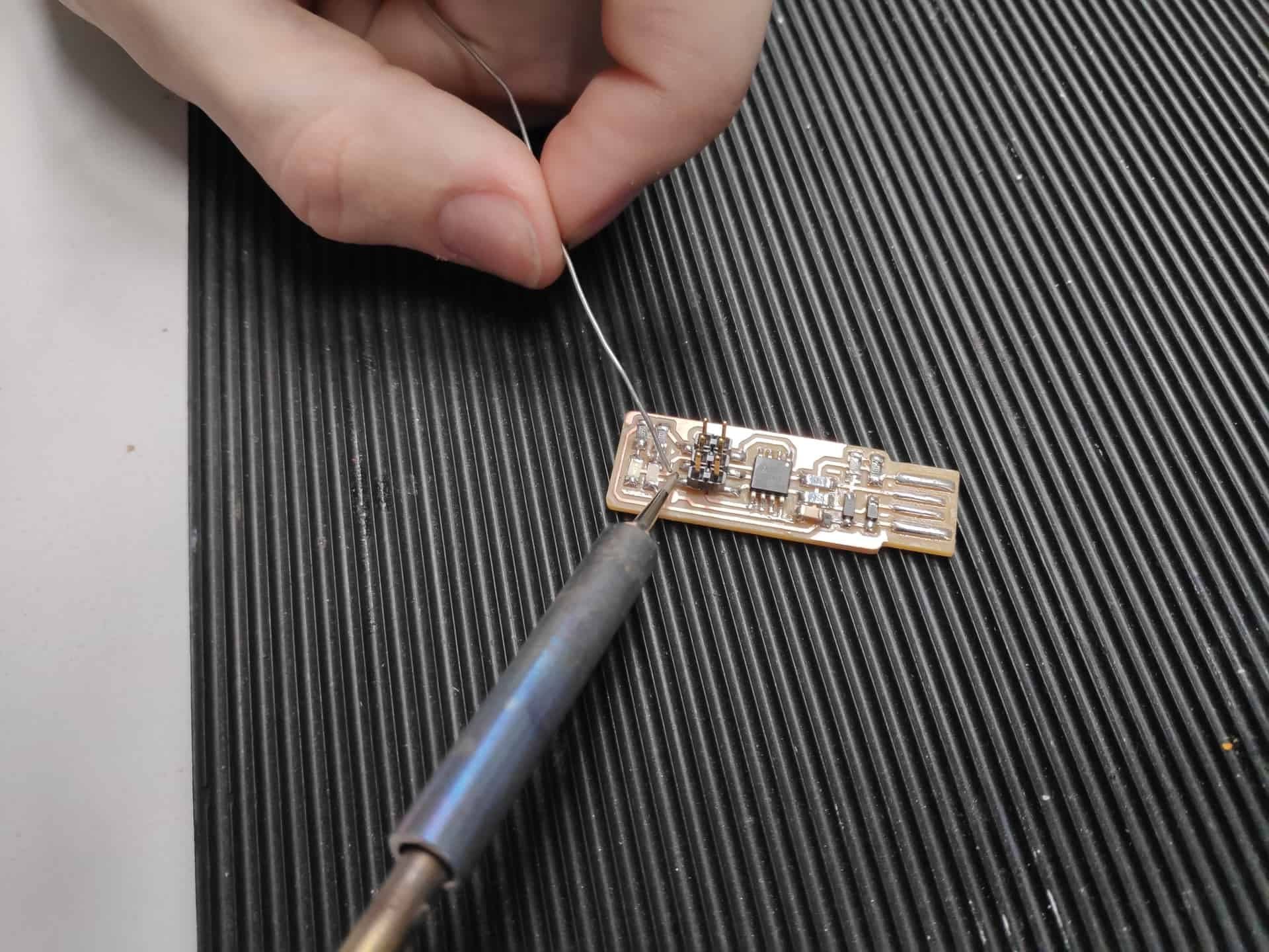
Tin the soldering iron by adding a small amount of solder and removing it using the wet sponge.
Tin one of the contacts for each of the resistors, capacitors and the diodes.
Do the same for one of the 6/8 legs of the Tiny Chips and the ISP
Place the components on top of the solder and use a pair of tweezers to push it towards the board, therefore keeping it still. This is the hardest step, as if you have tinned the pad with too much solder then you will find it difficult to hold the component next to the board.
Heat up the solder which you tinned onto the board and you should have attached the component onto the board.
Then solder the other end/legs of that component, going back to add more solder to the other leg/end if there isn’t enough.
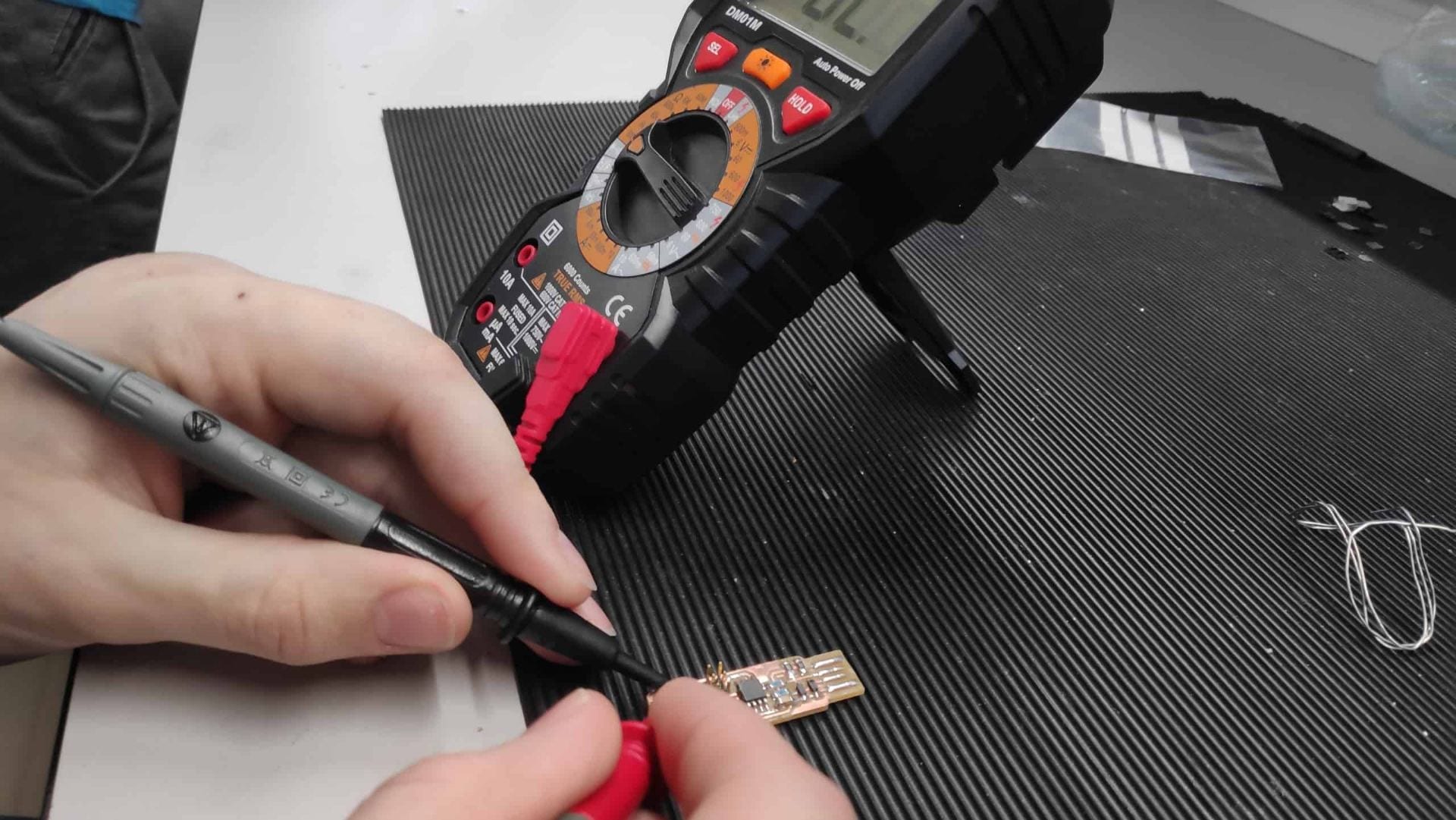
To test the connection you should use a multi-meter on the most sensitive resistance setting. This will check continuity between the component. If the reading is 0 or very near to 0 e.g 0.003 then there is a short whereas if there is a reading of around the size of the resistors measurement then you cave it correctly installed.
Check the overall circuit by applying 5v volts to the USB as in the diagram. S1 is shorted then the left LED should light up indicating that the circuit works.
Programming this chip requires it to be shorted and then the programming can begin.
Installing the software was harder than following the links due to the lack of clear instruction on what parts are needed, especially for Git. The link for Atmel GNU Toolchain wasnt correct so I am unsure which I needed to install. I typed what the link was supposed to take me to into google and cap up with this website. Download all the files as a zip and then extract them in the desired folder.
I decided to create a different programs folder so I could better keep track of the software on my computer. I didn’t want to destroy anything.
Installations complete – all of the tools are located in F:UNI ProgrammingPrograms
Updating the path
Control Panel > Advanced System Settings > Advanced tab > Environment Variables
Under User Variables > Edit for Path > See below
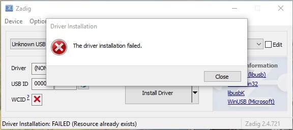
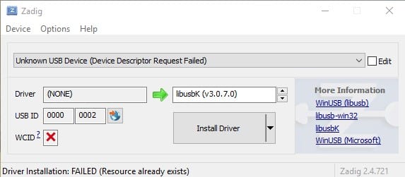
Next it to download Zadig and run this to install drivers for the USB > where I got stuck
Windows didn’t like the USB and so every attempt failed to install the drivers.
I checked here for shorts between VCC and ground and found nothing amiss so it is a possibility that my PC isn’t compatible and wont recognise the USB.
Checking software installations
> Type make -v in GitBash
> Type avr-gcc –version FAILED
> Type avrdude -c usbtiny -p t45 FAILED
UPDATE 2 > 04/03/2019
Going into the Fab Lab today helped so much after the failed attempts at home. The main different being using an iMac rather than a windows computer. Mike in the Fab Lab also says that Linux works very well, so maybe a possibility of having a separate partition on a hard drive to set up a Linux OS on my PC.
The steps are as follows for Mac with the software installed:
Customise the make file > Edit the line with MCU = attiny45
Customise the clock speed > Edit the line with F_CPU = 16500000UL
Edit the programmer used to program your board > PROGRAMMER ?= usbtiny
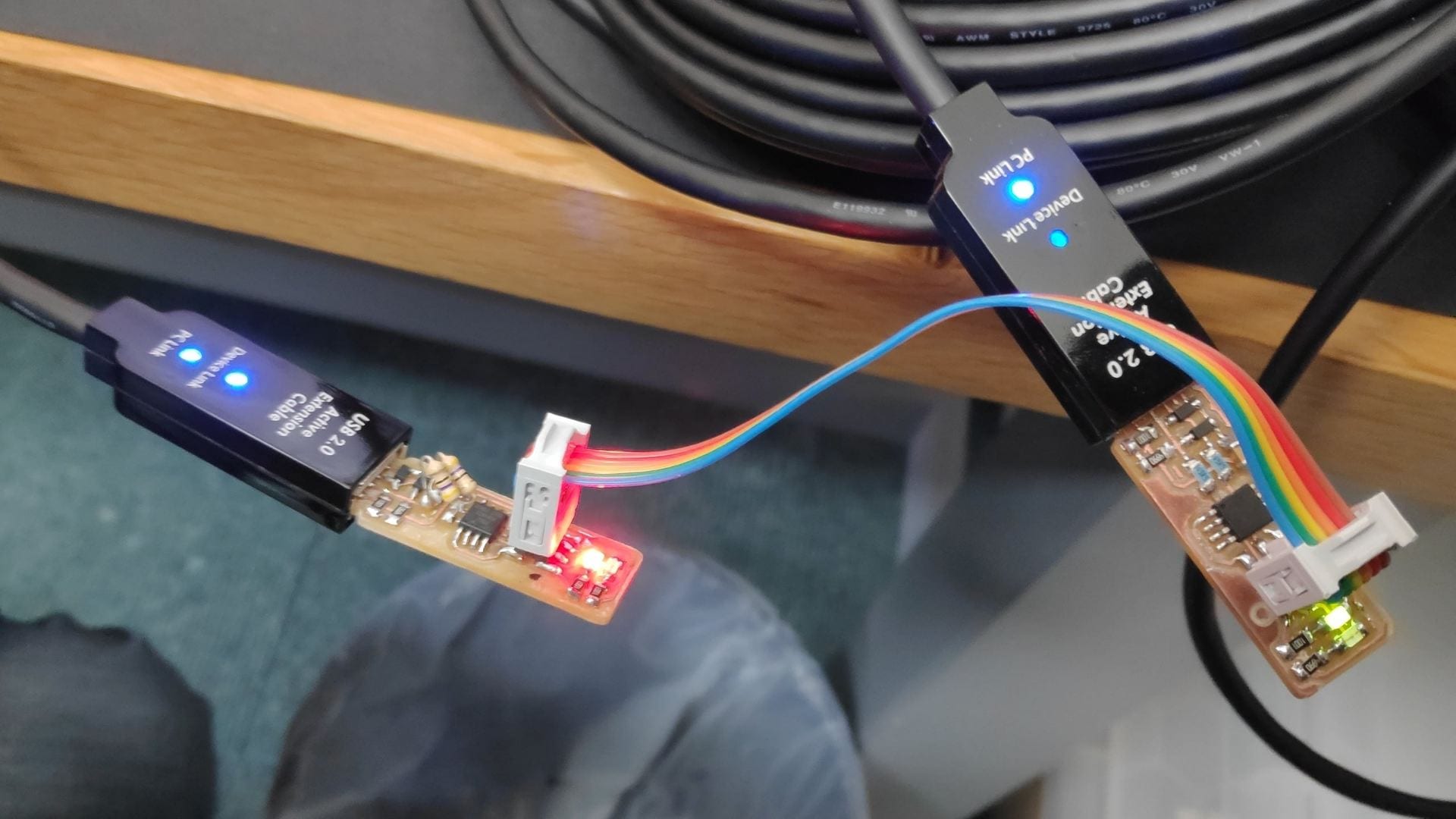
Plug in your board using a USB extension to not mess up your computer USB ports as well as the programmer > connect their 2 ISP headers with a ribbon cable in the correct orientation
Open the Terminal > type pwd to check path Enter
Type cd (space) (and drag the downloaded folder in) Enter
Type pwd to check > should be the path of your folder Enter
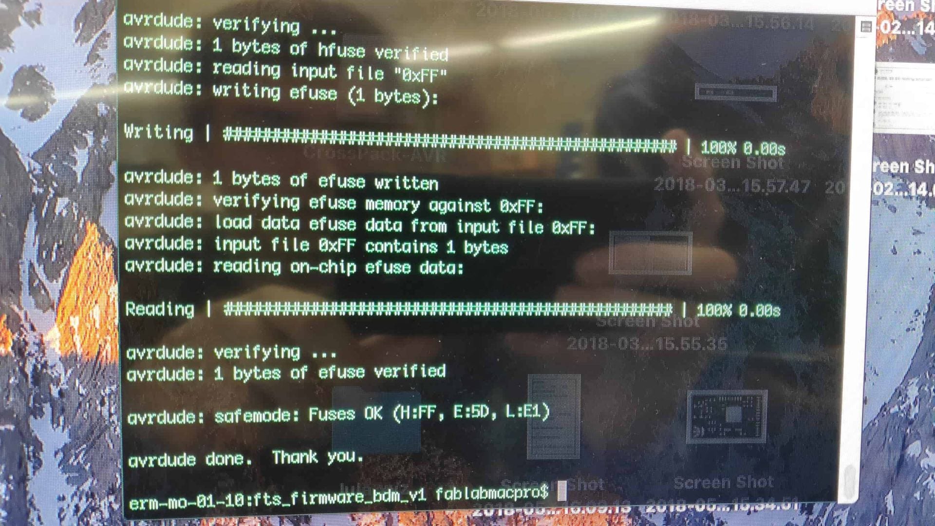
Type make flash > should come up with loading bars if working Enter
Type make fuses > should come up with loading bars if working Enter
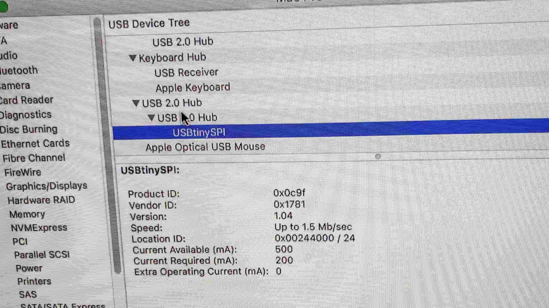
Unplug both > re-insert your board > check mac recognises device in the system information > should show usbtiny
Reattach programmer and ribbon cable
Type makerstdisbl > blows reset fuse> should come up with loading bars if working Enter
Remove solder bridge if successful and you should now have a programmer
The programmer was then successfully tested using Andrew’s code to a board containing an LED and switch.
Multiple programs were tested and all were successful.
Task: Produce a press fit kit (accounting for kerf) using the laser cutter
Making the Design
The main aim is to use parametric design software to ‘simplify the process’. Being able to edit the sketch automatically by adding parameters and using these to dimension the sketch instead of manually changing them.
First step was to create the rough design on Fusion 360 and then dimension it to ensure that it would fit together.
As you can see above the dimension with fx: 2.5 are the parameter dimensions. These are controlled by the parameter menu and are what you use to account for the kerf using these identities below: See my post about how to use parameters
+ addition
– subtraction
* multiplication
/ division
^ power
( following BIDMAS
) following BIDMAS
; delimiter for multi argument functions
Laser power settings were already determined my John and Gary on the saved power settings
Working out the kerf of the laser cutter is different for every material, due to the taper that it puts on when cutting. I worked out that the kerf was 0.125mm for 4mm Acrylic which is what I chose to make my model from. I decided to skip the card model as I felt it wouldn’t work very well with the clip mechanism that I was going to use and time would be better spent making it with either acrylic or MDF.
Overall 18 different versions were made on Fusion 360 to get the fit just right, and by doing several cuts using the laser cutter i worked out the correct tolerance as well as the correct dimension for the clip ‘nubs’. I do however have a graveyard of broken acrylic parts to show for it! The clips works by having a ‘nub’ which sticks out and slots into a cut out hole on the other piece. This allows the model to go together but it won’t came apart once assembled.
Assembling the completed part in Fusion was also relatively easy, although not as intuitive as Solidworks – much prefer Solidworks as it gives more control and the interface is more technical.
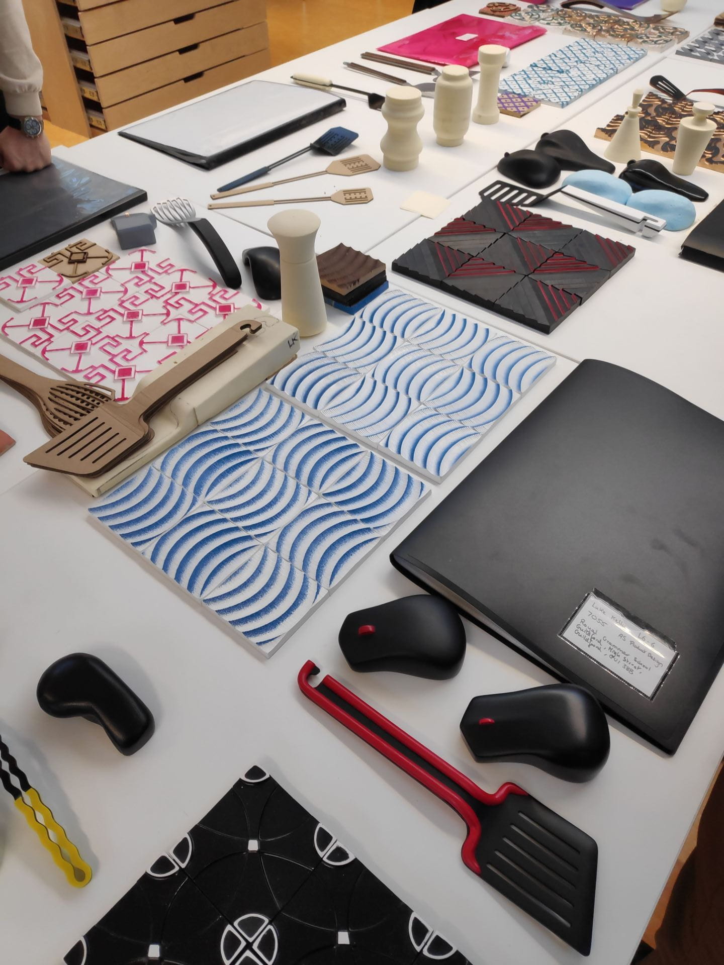
The task this week was to make on Fusion 360 a version of our tile, render it and display it as a pattern of 9.
Method
Start new sketch > Draw 100 x 100 mm square using corner to corner rectangle tool > Exit sketch
Extrude 13mm with a taper of 4 degrees (minimum required draft angle to help release castings from the mould)
To make a draft angle you need to input a taper value of less than -4
Using the arc tool, curves were created to be the path for the sweep and circles were created to become the profile of the sweep action. Relatively simple to do once the lines were in place, but due to the draft angle, mis-clicks were common.
Using the sweep tool, the ‘waves’ in the top of the tile were created, by basically removing anything which intersected with the square extrusion
Creating the ‘waves’ using the sweep command
Overall it was quite a simple process to create my tile, although learning the software at the same time doesn’t help. Once I knew how to operate the commands, and which ones were used for making it, it could be made relatively quickly – under 8 minutes.
Mistakes –
I originally tried to use the sweep by just using an arc as a profile curve which didn’t work. Fusion 360 requires a surface to create an extrusion and I was unsure how to make the arc into a closed curve and then hopefully a surface.
Making the ‘Assembly’
I used this link to learn quickly how to copy and paste and move objects around to create an assembly in Fusion 360. While it still works, I prefer the Solidworks Assembly, due to it focusing entirely on the assembly, rather than on making the model, as well.
Rendering
Rendering is using CAD to provide a lifelike image of your model so that colours and form can be better understood without actually making a physical model. It is the next best thing to making physical models especially in the design phase when there may be many different ideas that need to be modelled.
Help Menu > Solidworks tutorials is a good place to go if stuck
GrabCAD is an online source of downloadable CAD files which can help you to learn how they made a model – with the feature tree you can see every step of them making the model
I have used Lynda.com to start learning Solidworks